EasyManuals Logo

D-Link DGS-1510 Series Hardware Installation Guide

D-Link DGS-1510 Series
64 pages
To Next Page IconTo Next Page
To Previous Page IconTo Previous Page
Page #21 background imageLoading...
Page #21 background image
DGS-1510 Series Gigabit Ethernet SmartPro Switch Hardware Installation Guide
21
Power Failure (AC Power)
In the event of a power failure, just as a precaution, unplug the power cord from the Switch. After the
power returns, plug the power cord back into the power soket of the Switch.
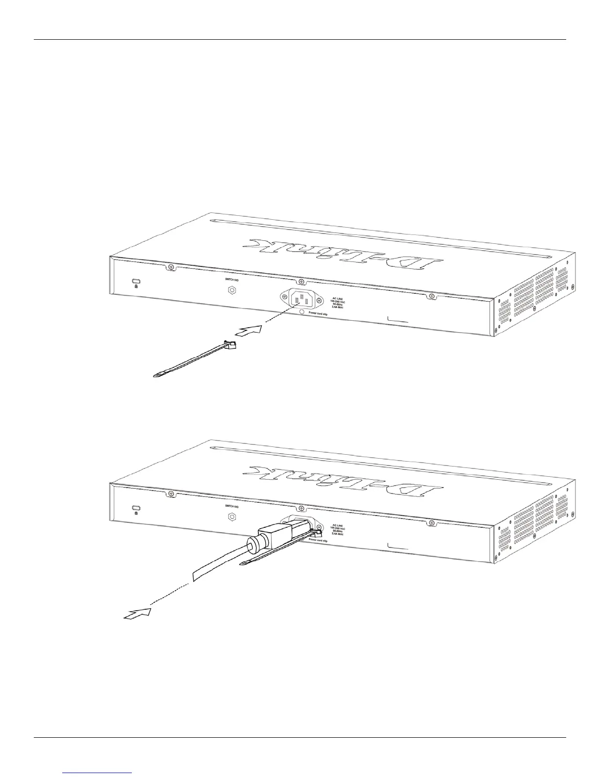
Installing Power Cord Clip
To prevent accidental removal of the AC power cord, it is recommended to install the power cord clip
together with the power cord.
1. With the rough side facing down, insert the Tie Wrap into the hole below the power socket.
Figure 2-5 Insert Tie Wrap to the Switch
2. Plug the AC power cord into the power socket of the Switch.
Figure 2-6 Connect the power cord to the Switch
3. Slide the Retainer through the Tie Wrap until the end of the cord.

Table of Contents

Other manuals for D-Link DGS-1510 Series

Questions and Answers:

Question and Answer IconNeed help?

Do you have a question about the D-Link DGS-1510 Series and is the answer not in the manual?

D-Link DGS-1510 Series Specifications

General IconGeneral
LayerLayer 2+
IGMP SnoopingYes
Static RoutingYes
Humidity10% to 90% non-condensing
SeriesDGS-1510
TypeSmart Managed Switch
VLAN SupportYes
QoSYes
ManagementWeb-based, CLI, SNMP
Power SupplyInternal
MAC Address Table16K entries
802.3ad Link AggregationYes
Spanning Tree Protocol (STP)Yes, STP/RSTP/MSTP
Jumbo Frame SupportYes, up to 9KB
Power ConsumptionVaries by model
DimensionsVaries by model
WeightVaries by model
Operating Temperature0°C to 40°C
Storage Temperature-40°C to 70°C
Standards ComplianceIEEE 802.3, IEEE 802.3u, IEEE 802.3ab, IEEE 802.3x, IEEE 802.3ad, IEEE 802.1D, IEEE 802.1w, IEEE 802.1s, IEEE 802.1Q, IEEE 802.1p

Related product manuals