EasyManuals Logo

D-Link DXS-3400 SERIES Hardware Installation Guide

D-Link DXS-3400 SERIES
61 pages
To Next Page IconTo Next Page
To Previous Page IconTo Previous Page
Page #42 background imageLoading...
Page #42 background image
DXS-3400 Series Lite Layer 3 Stackable 10GbE Managed Switch Hardware Installation Guide
42
Appendix B - Cables and Connectors
Ethernet Cable
When connecting the Switch to another switch, a bridge or hub, a straight-through Cat5/5e/6a/7 cable is necessary.
Please review these products for matching cable pin assignment.
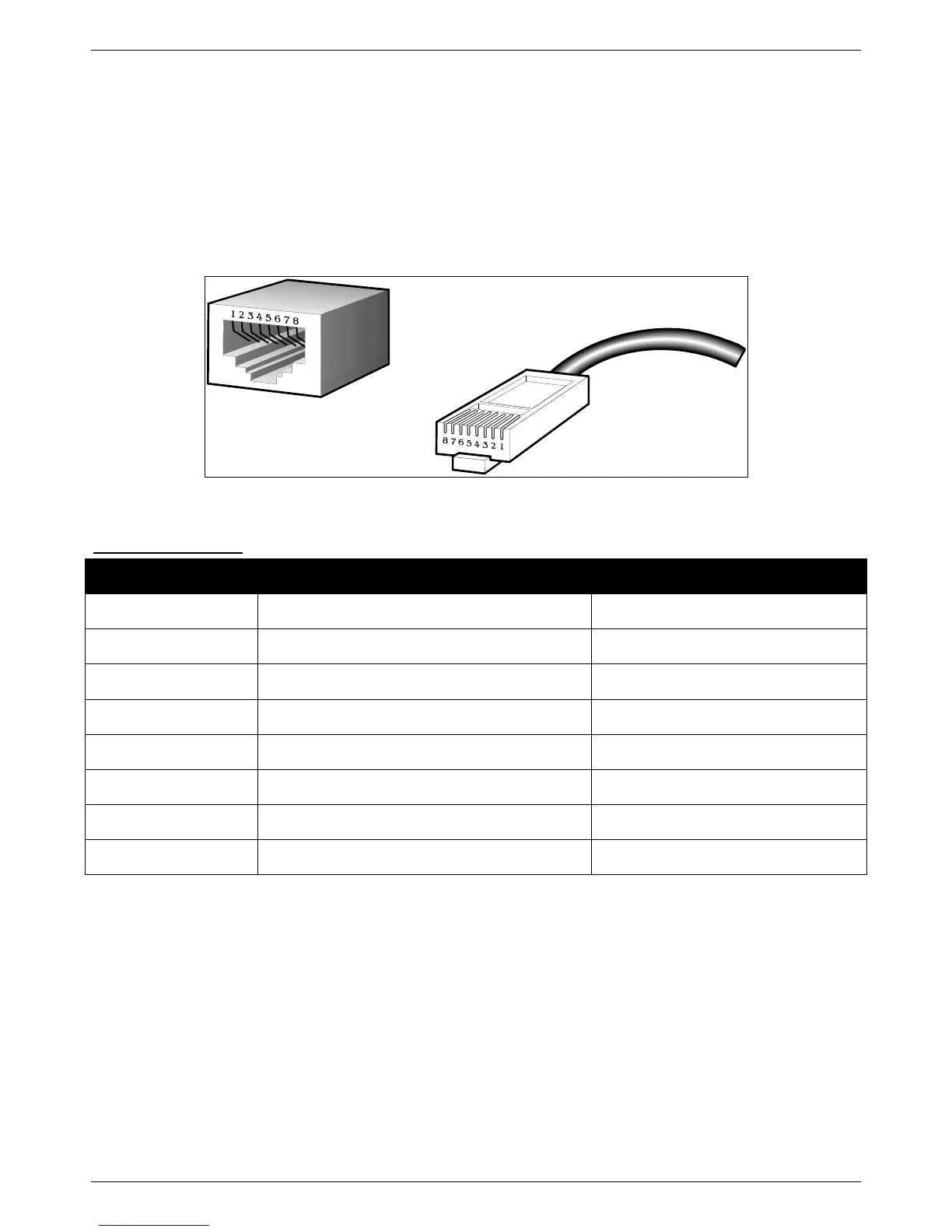
The following diagrams and tables show the standard RJ45 socket/connector and their pin assignments.
Figure B-1 Standard RJ45 socket and connector pin assignments
RJ45 Pin Assignment
Contact
MDI-X Port
MDI-II Port
1
RD+ (receive)
TD+ (transmit)
2
RD - (receive)
TD - (transmit)
3
TD+ (transmit)
RD+ (receive)
4
1000BASE-T
1000BASE-T
5
1000BASE-T
1000BASE-T
6
TD - (transmit)
RD - (receive)
7
1000BASE-T
1000BASE-T
8
1000BASE-T
1000BASE-T

Table of Contents

Other manuals for D-Link DXS-3400 SERIES

Questions and Answers:

Question and Answer IconNeed help?

Do you have a question about the D-Link DXS-3400 SERIES and is the answer not in the manual?

D-Link DXS-3400 SERIES Specifications

General IconGeneral
BrandD-Link
ModelDXS-3400 SERIES
CategoryNetwork Router
LanguageEnglish

Related product manuals