xStack
®
DES-3528/DES-3552 Series Layer 2 Managed Stackable Fast Ethernet Switch Hardware Installation Guide
Section 3
Connecting the Switch
Switch to End Node
Switch to Hub or Switch
Connecting To Network Backbone or Server
NOTE: All 24/48 high-performance NWay Ethernet ports can support both
MDI-II and MDI-X connections.
Switch to End Node
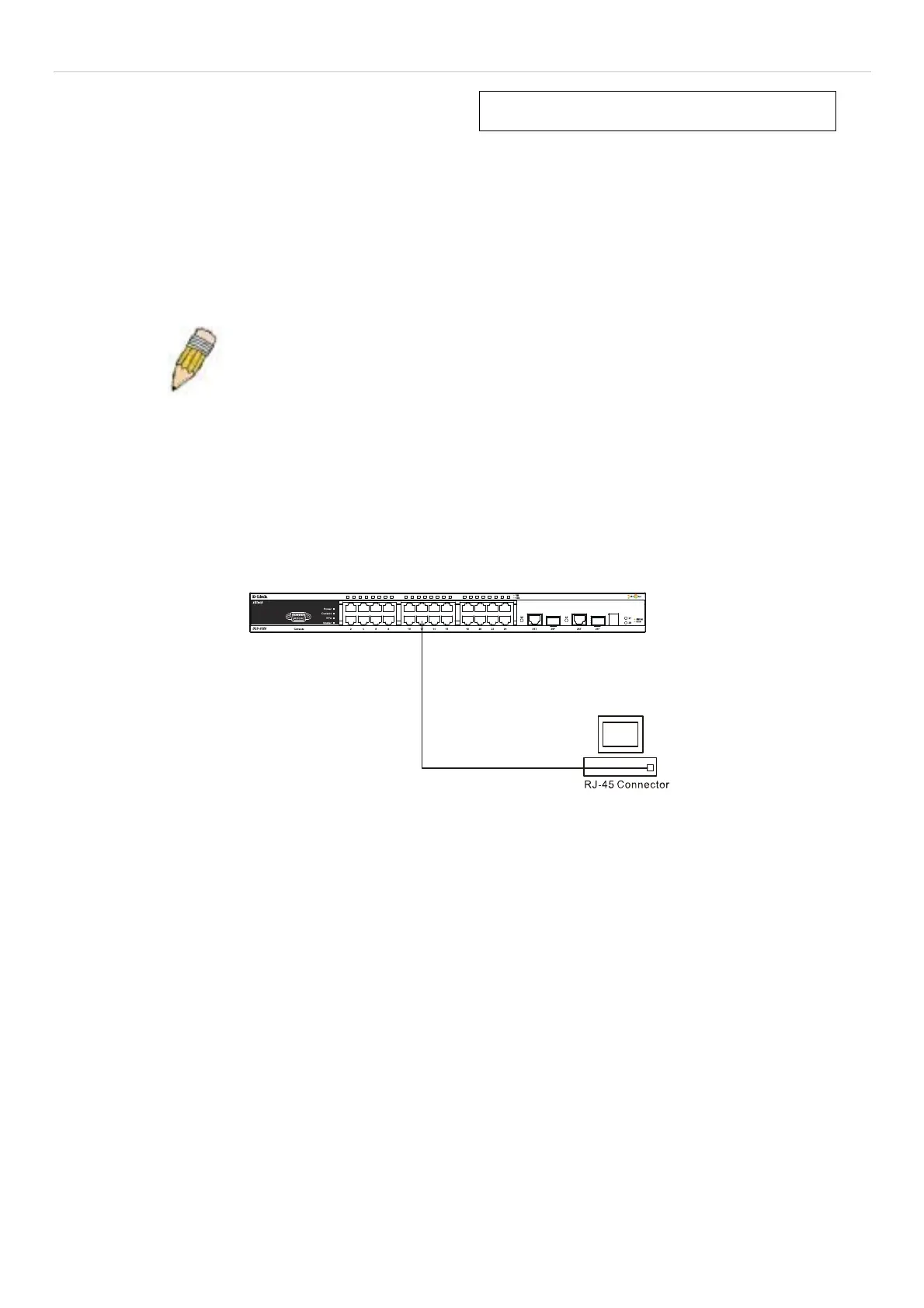
End nodes include PCs ou tfitted with a 10, 100 or 1000 Mbps RJ-45 Ethernet/F ast Ethernet Network Interface Ca rd
(NIC) and most routers.
An end no de can be connected to the Switch via a twisted-pair Category 3, 4, or 5 UTP/ STP cable. T he end n ode
should be connected to any of the ports of the Switch.
Figure 3- 1. The Switch connected to an end node
The Link/Act LEDs for each UTP port will light green or amber when the link is valid. A blinking LED indicates packet
activity on that port.
Switch to Hub or Switch
These connections can be accomplished in a number of ways using a normal cable.
A 10BASE-T hub or switch can be connected to the Switch via a twisted-pair Category 3, 4 or 5 UTP/STP cable.
A 100BASE-TX hub or switch can be connected to the Switch via a twisted -pair Category 5 UTP/STP cable.
A 1000BASE-T hub or switch can be connected to the Switch via a twisted -pair Category 5E UTP/STP cable.
15

 Loading...