www.d3engineering.com 585.429.1550
D3Engineering.com ▪ 585.429.1550
DesignCore™ TDA3x Product Family ▪ Quick Start Guide
Document No. 00C-131 ▪ Version 1.0 ▪ Release Date: 1/17/2019
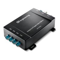
4. To access most of the debugging and video interfaces for the RVP-TDA3x ADAS
Development Kit, remove the Access Panel, which is marked on the RVP-TDA3x module,
shown below. This panel is held in by two captive 4-40 screws.
Access panel location on RVP-
TDA3x module, showing captive 4-
40 bolts holding it in
5. The next step involves connecting the RVP-TDA3x module to a computer to access the
debug Serial console. Connect the provided USB-USB Micro B cable to the serial port, as
shown below.
USB Micro B cable connected to
the Serial console debug port
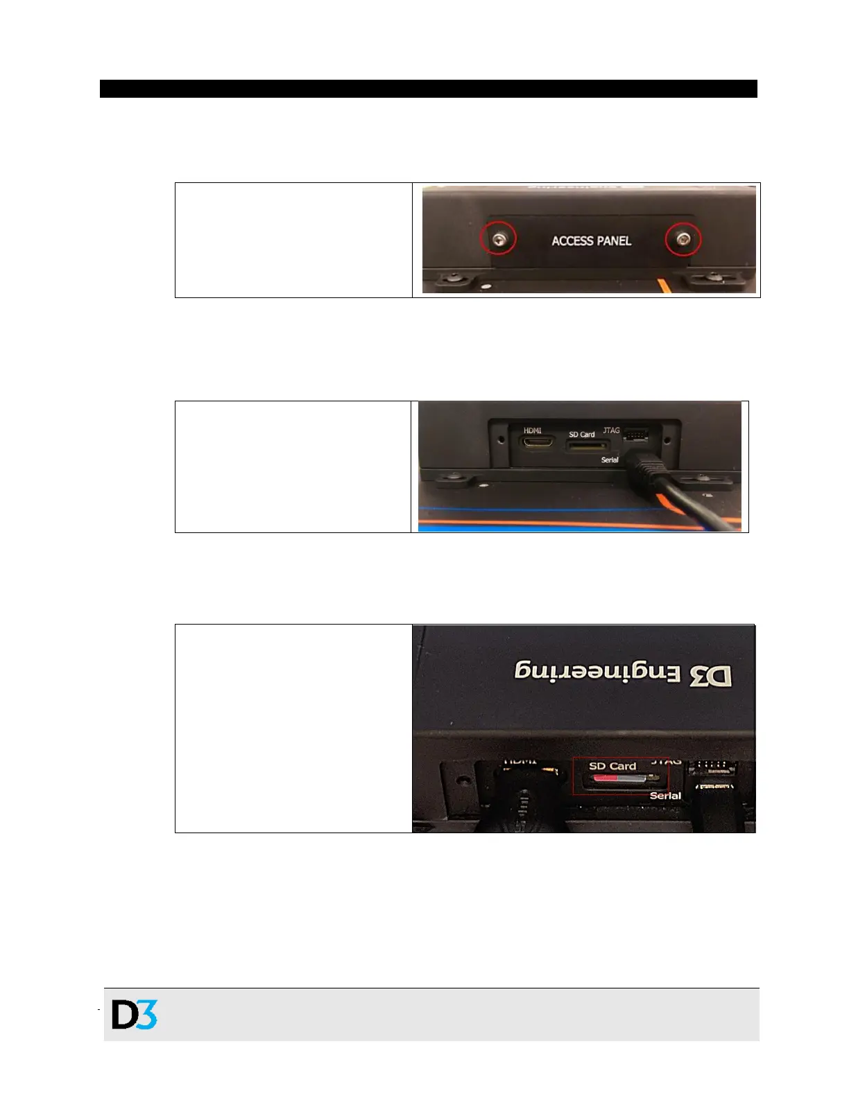
6. Next, insert the provided Micro SD Card into the marked SD Card slot on the RVP-TDA3x
system, as shown below. The device will not boot without this card inserted.
Micro SD Card inserted into RVP-
TDA3x system
 Loading...