8 | Piping installation
Installer reference guide
63
EPGA11~16DAV3(7) + EAVZ16S18+23DA6V(7)+9W
Daikin Altherma 3 H F
4P556075-1A – 2021.09
T1
M1
T1
M1
T2
M2
T3
M3
M
FHL1
FHL2
FHL3
M2 M3
T2 T3
HPC1 HPC2 HPC3
b
g hf
d e
i
i
hh
h
h
j
ca
h
h
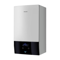
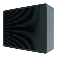
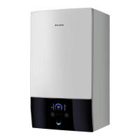
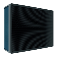
a Outdoor unit
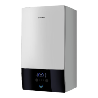
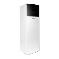
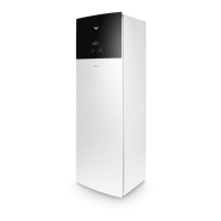
b Indoor unit
c Heat exchanger
d Backup heater
e Motorised 3‑way valve (mixing the main zone)
f Additional pump
g Main pump
h Shut-off valve
i Collector (field supply)
j Overpressure bypass valve (delivered as accessory)
FHL1...3 Floor heating loop (field supply)
HPC1...3 Heat pump convector (field supply)
T1...3 Individual room thermostat (optional)
M1...3 Individual motorised valve to control loop FHL1...3 and HPC1...3 (field supply)
Maximum water volume
NOTICE
The maximum water volume depends on whether glycol is added to the water
circuit. For more information on the addition of glycol, refer to "8.2.6To protect the
water circuit against freezing"[470].
Use the following graph to determine the maximum water volume for the
calculated pre-pressure.
20
2,4
2,1
1,8
1,5
1,2
0,9
1
0,6
0,3
70 120
175
140 200 255
220
270
A
B
A Pre-pressure (bar)
B Maximum water volume (l)
Water
Water + glycol
Example: Maximum water volume and expansion vessel pre-pressure
 Loading...
