EasyManua.ls Logo

Daikin DZ9VC User Manual

Daikin DZ9VC
40 pages
To Next Page IconTo Next Page
Page #1 background imageLoading...
Page #1 background image
Our continuing commitment to quality products may mean a change in specications without notice.
© 2022
19001 Kermier Rd., Waller, TX 77484
www.daikincomfort.com

The following symbols and labels are used throughout this
manual to indicate immediate or potential safety hazards. It
is the owner’s and installer’s responsibility to read and comply
with all safety information and instructions accompanying
these symbols. Failure to heed safety information increases
the risk of personal injury, property damage, and/or product
damage.
Also see “Meanings of Symbols” on page 4.
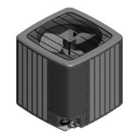
HEAT PUMP UNIT
DZ9VC HEAT PUMP
INSTALLATION & SERVICE REFERENCE
INSTALLATION INSTRUCTIONS
IOD-4042
12/2022
Index
 1
 2
 2
 2
 2
 3
 3
 4
 7
 7
 8
 8
 15
 17
 21
 23
 29

32
 33
“IMPORTANT – This product has been designed and manufactured to meet ENERGY STAR criteria for energy
e󰀩ciency when matched with appropriate coil components. However, proper refrigerant charge and proper air
ow are critical to achieve rated capacity and e󰀩ciency. Installation of this product should follow the manu-
facturer’s refrigerant charging and air ow instructions. 
󰀩
WARNING
HIGH VOLTAGE
DISCONNECT ALL POWER BEFORE SERVICING
OR INSTALLING THIS UNIT. MULTIPLE POWER
SOURCES MAY BE PRESENT. FAILURE TO DO SO
MAY CAUSE PROPERTY DAMAGE, PERSONAL
INJURY OR DEATH.
ONLY PERSONNEL THAT HAVE BEEN TRAINED TO INSTALL,
ADJUST, SERVICE OR REPAIR(HEREINAFTER, “SERVICE”)
THE EQUIPMENT SPECIFIED IN THIS MANUAL SHOULD
SERVICE THE EQUIPMENT. THE MANUFACTURER WILL
NOT BE RESPONSIBLE FOR ANY INJURY OR PROPERTY
DAMAGE ARISING FROM IMPROPER SERVICE OR SERVICE
PROCEDURES. IF YOU SERVICE THIS UNIT, YOU ASSUME
RESPONSIBILITY FOR ANY INJURY OR PROPERTY
DAMAGE WHICH MAY RESULT. IN ADDITION, IN
JURISDICTIONS THAT REQUIRE ONE OR MORE LICENSES
TO SERVICE THE EQUIPMENT SPECIFIED IN THIS
MANUAL, ONLY LICENSED PERSONNEL SHOULD SERVICE
THE EQUIPMENT.
IMPROPER INSTALLATION, ADJUSTMENT, SERVICING OR
REPAIR OF THE EQUIPMENT SPECIFIED IN THIS MANUAL,
OR ATTEMPTING TO INSTALL, ADJUST, SERVICE OR REPAIR
THE EQUIPMENT SPECIFIED IN THIS MANUAL WITHOUT
PROPER TRAINING MAY RESULT IN PRODUCT DAMAGE,
PROPERTY DAMAGE, PERSONAL INJURY OR DEATH.
WARNING
WARNING
DO NOT BYPASS SAFETY DEVICES

Questions and Answers:

Daikin DZ9VC Specifications

General IconGeneral
StagesVariable
Heating Seasonal Performance Factor (HSPF)Up to 10
RefrigerantR-410A
TypeVariable Speed
Heating Capacity24, 000-60, 000 BTU/hr
Seasonal Energy Efficiency Ratio (SEER)Up to 19
Indoor Unit Noise LevelVariable
Power Supply208/230V
Indoor Unit DimensionsVaries by model
Outdoor Unit DimensionsVaries by model
Indoor Unit WeightVaries by model
Outdoor Unit WeightVaries by model

Summary

Important Safety Instructions

High Voltage and Personnel Safety

Critical safety warnings regarding high voltage, qualified personnel, and bypassing safety devices.

Installation and Compliance

Shipping Inspection and Codes

Procedures for inspecting shipments and complying with installation codes and regulations.

Installation Clearances

Specifies required distances from structures and obstructions for proper airflow.

Installation Best Practices

Rooftop and Noise Considerations

Guidelines for rooftop installations and minimizing electrical noise transmission.

General Installation Safety

Emphasizes using licensed installers and careful handling to prevent hazards.

Refrigerant Safety and Handling

Refrigerant Hazards and Cylinder Safety

Details risks associated with refrigerants and safe practices for handling cylinders.

Refrigerant Line Installation

Covers proper installation of refrigerant lines, including tubing and insulation.

Installation Procedures and Warnings

Grounding and Power Supply

Instructions for proper grounding and ensuring adequate power supply circuits.

Refrigerant Line Protection

Guidelines for protecting refrigerant lines from damage and ensuring proper installation.

Refrigerant System Service

Line Connections and Brazing

Procedures for connecting and brazing refrigerant lines, including filter drier installation.

Leak Testing and Evacuation

Steps for performing pressure tests, leak detection, and system evacuation.

System Evacuation and Start-Up

Deep Vacuum Method

Recommended procedure for evacuating the system to remove moisture and air.

Start-Up and Electrical Connections

Details on system start-up, electrical connections, and safety precautions.

Electrical Wiring and Grounding

Power Wiring and Grounding

Guidelines for high-voltage power supply wiring, grounding, and safety devices.

Low Voltage and Thermostat Wiring

Instructions for connecting low voltage communication and thermostat wiring.

System Wiring and Charging

Indoor/Outdoor Wiring and Connection

Explains typical wiring configurations and connecting the heat pump unit to the system.

Refrigerant Charge Calculation

Method for calculating and adding refrigerant based on line set length.

Refrigerant Charge Adjustment

System Start-up and Subcooling

Procedures for system start-up, refrigerant adjustment, and subcooling measurement.

Operational Modes and Features

Temperature Lock-outs and Boost Mode

Configuration of outdoor temperature lock-outs and the field-selectable Boost Mode.

Dehumidification Functionality

How the system manages humidity using cooling and airflow adjustments.

System Control and Diagnostics

Dehumidification Tips and Advanced Features

Best practices for dehumidification and overview of Daikin One+ system features.

Error History and Monitoring

Accessing and interpreting error history and system status for troubleshooting.

Cooling Airflow Profiles

Descriptions of different cooling airflow patterns (A, B, C, D) for performance tuning.

Advanced System Settings

Dehumidification Select and Airflow Trim

Options for selecting dehumidification modes and adjusting airflow trims.

Compressor Speed and Heat Settings

Adjusting maximum compressor speed and heat performance variables.

Wiring Diagrams

2-Ton Unit Wiring

Visual representation of the electrical connections for the 2-ton heat pump unit.

Wiring Diagrams

3-5 Ton Unit Wiring

Visual representation of the electrical connections for the 3-5 ton heat pump units.

Component Testing

Capacitor Resistance Test

Procedure for safely testing capacitor resistance on the unit's control board.

Component Testing

Capacitor Test for 3-5 Ton Units

Specific guidance for testing capacitor resistance on 3-5 ton models.

Heating Performance Analysis

Heating Troubleshooting Guide

A chart correlating system issues with probable causes in heating mode.

Cooling Performance Analysis

Cooling Troubleshooting Guide

A chart correlating system issues with probable causes in cooling mode.

Troubleshooting Overview

Outdoor Unit Dipswitch Settings

Default factory settings for dipswitches on the outdoor control board.

Network Troubleshooting

Communication Error Resolution

Steps to diagnose and resolve network communication errors using LEDs and system resets.

Mode Display Operations

Display Navigation and Modes

Overview of the 3-digit display, button functions, and available operating modes.

Display Screen Navigation

Navigating Through System Screens

Step-by-step instructions for moving between different display screens.

Fault Code History

Accessing Fault Code History

Procedure for viewing the six most recent system fault codes.

Monitoring Mode Usage

Monitoring System Variables

Guide on how to monitor various system parameters and values.

Setting Mode 1 Operations

Adjusting System Settings (Mode 1)

Instructions for modifying system settings related to airflow and fan delays.

Setting Mode 2 Operations

Adjusting System Settings (Mode 2)

Instructions for modifying system settings related to defrost and Boost Mode.

7-Segment Display Functions

Fault Code and Monitor Screens

Details on using the display for fault codes and monitoring system status.

7-Segment Display Settings (Mode 1)

Setting Mode 1 Configurations

Specific settings for airflow trims, profiles, and dehumidification selection.

7-Segment Display Settings (Mode 2)

Setting Mode 2 Configurations

Specific settings for defrost intervals, compressor speed, and Boost Mode.

Homeowner Maintenance and Support

Routine Maintenance and Troubleshooting Tips

Recommendations for homeowners on filter cleaning and basic troubleshooting steps.

Start-Up Checklist

System Checks and Measurements

Checklist for electrical, temperature, pressure, superheat, and subcooling measurements.

Troubleshooting: Fault Codes

Fault Code Analysis (Part 1)

Troubleshooting table covering various fault codes, their probable causes, and corrective actions.

Troubleshooting: Fault Codes

Fault Code Analysis (Part 2)

Continues the troubleshooting table with faults related to temperature and leaks.

Troubleshooting: Fault Codes

Fault Code Analysis (Part 3)

Continues the troubleshooting table addressing voltage, compressor, and refrigerant issues.

Troubleshooting: Fault Codes

Fault Code Analysis (Part 4)

Continues the troubleshooting table for airflow, communication, and data errors.

Product Information and Feedback

Customer Feedback and Registration

Information on providing product feedback and registering for warranty protection.

Related product manuals