6 Electrical installation
Installation manual
31
EBSH/X(B)11+16P50D
Daikin Altherma 3 R ECH₂O
4P759878-1 – 2024.01
3 Fix the cables with cable ties to the cable tie mountings.
In case of high voltage Smart Grid contacts
Wires (Smart Grid pulse meter): 0.5mm²
Wires (high voltage Smart Grid contacts): 1mm²
[9.8.4]=3 (Benefit kWh power supply = Smart Grid)
[9.8.5] Smart Grid operation mode
[9.8.6] Allow electrical heaters
[9.8.7] Enable room buffering
[9.8.8] Limit setting kW
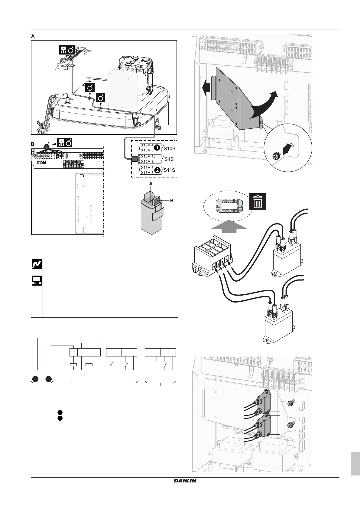
The wiring of the Smart Grid in case of high voltage contacts is as
follows:
S4S
910
X 5M1X 5M1
78
K2AK1A
5634
K1ALNL
A1
A2
25242523X1 M2
K2A
A1
A2
2 1
STEP 1 Smart Grid relay kit installation
STEP 2 Low voltage connections
STEP 3 High voltage connections
High voltage Smart Grid contact 1
High voltage Smart Grid contact 2
a, b Coil sides of relays
c, d Contact sides of relays
e Jumper (factory-mounted). If you also connect a safety
thermostat (Q4L), replace the jumper with the safety
thermostat wires.
f Smart Grid pulse meter
1 Install the switch box metal insert.
2 Loosen the cables connected to the terminal of the Smart Grid
relay kit (EKRELSG) and remove the terminal.
3 Install the components of the Smart Grid relay kit as follows: