10 Technical data
Installation manual
46
EBSH/X(B)11+16P50D
Daikin Altherma 3 R ECH₂O
4P759878-1 – 2024.01
10 Technical data
A subset of the latest technical data is available on the regional Daikin website (publicly accessible). The full set of the latest technical data is
available on the Daikin Business Portal (authentication required).
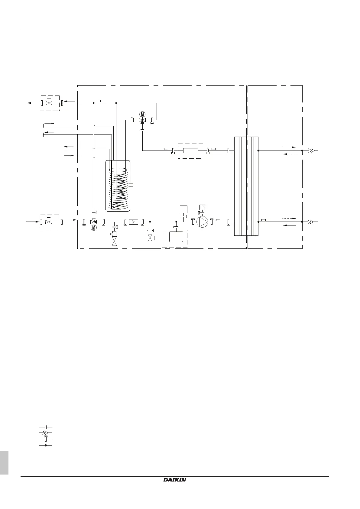
10.1 Piping diagram: Indoor unit
R1T
A
B
B
a2
a1
h
i
k
m
e
f
g
g
l
l
C
B
B1PW
3D136151B
b2
d1
b1
d2
l
l
l
l
R3T
n
c2
c4
c3
c1
D
R5T
R8T
M2S
B2L
R4T
j
R2T
R7T
M1S
A Indoor unit
B Field installed
C Optional
D Refrigerant side
a1 Space heating/cooling – Water IN (screw connection, 1")
a2 Space heating/cooling – Water OUT (screw connection, 1")
b1 DHW – Cold water IN (screw connection, 1")
b2 DHW – Hot water OUT (screw connection, 1")
c1 Gas refrigerant IN (heating mode; condenser)
c2 Liquid refrigerant IN (cooling mode; evaporator)
c3 Gas refrigerant OUT (cooling mode; evaporator)
c4 Liquid refrigerant OUT (heating mode; condenser)
d1 Water IN from bivalent heat source (screw connection, 1")
d2 Water OUT to bivalent heat source (screw connection, 1")
e Pump
f Backup heater
g Shut-off valve, female-female 1"
h Expansion vessel
i Drain valve
j Automatic air purge valve
k Safety valve
l External thread 1"
m External thread 3/4"
n Plate heat exchanger
B2L Flow sensor
B1PW Space heating water pressure sensor
M1S Tank valve
M2S Bypass valve
R1T Thermistor (plate heat exchanger - water OUT)
R2T Thermistor (backup heater – water OUT)
R3T Thermistor (Refrigerant liquid side)
R4T Thermistor (Inlet water)
R5T, R8T Thermistor (tank)
R7T Thermistor (tank - water OUT)
Screw connection
Flare connection
Quick coupling
Brazed connection