4 Unit installation
Installation manual
13
EBSH/X(B)11+16P50D
Daikin Altherma 3 R ECH₂O
4P759878-1 – 2024.01
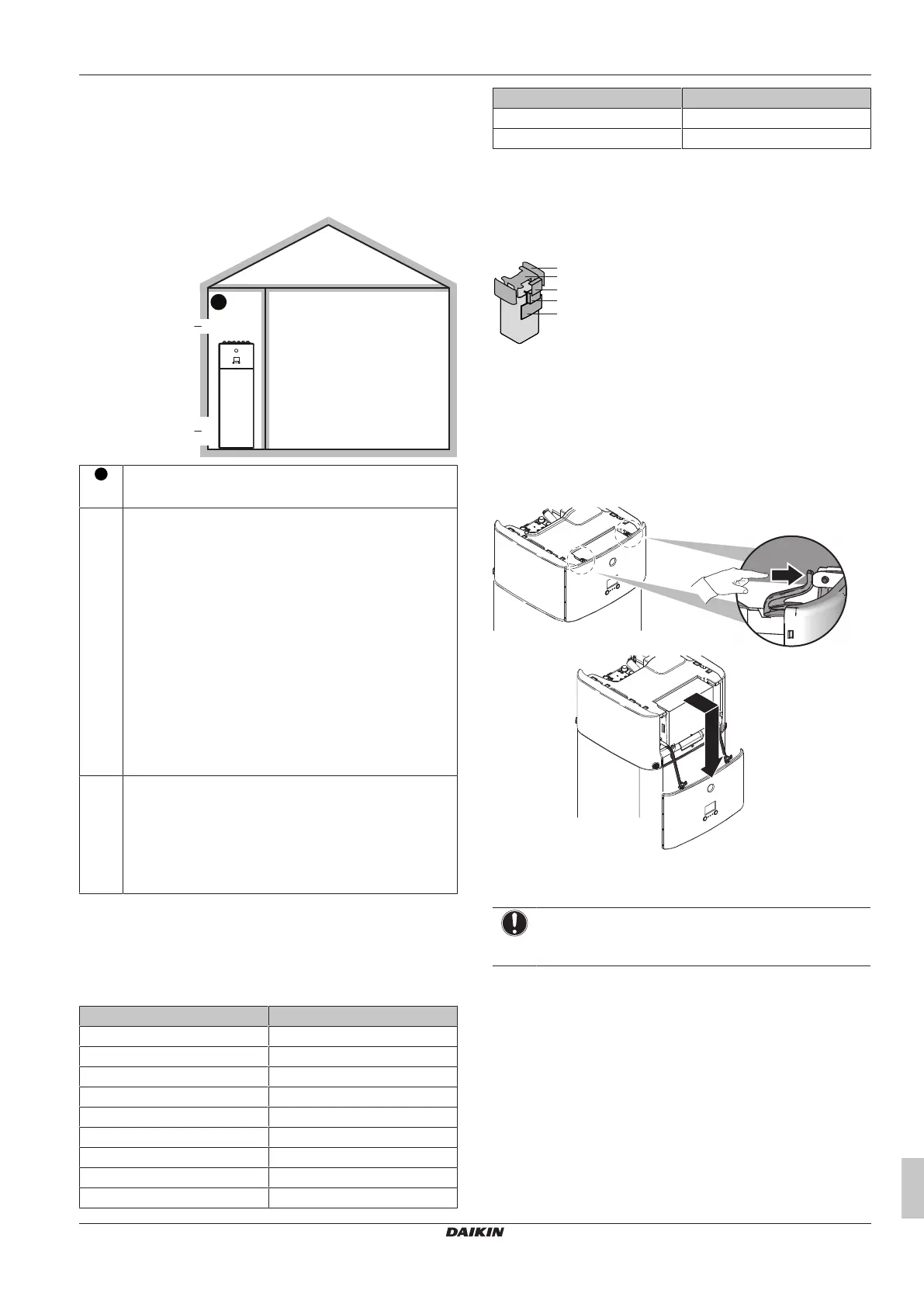
PATTERN 4
PATTERN 4 is only allowed for installations in technical rooms (i.e.
room that is NEVER occupied by persons). For this pattern there are
no requirements to the minimum floor area if you provide 2 openings
(one at the bottom, one at the top) between the room and the
outside to ensure natural ventilation. The room must be protected
from frost.
A
nv
(≥A
nv-min
)
Min. 50% of A
nv-min
a2
a1
A
Unoccupied room where the indoor unit is installed.
Must be protected from frost.
a1 A
nv
: Bottom opening for natural ventilation between the
unoccupied room and the outside.
▪ Must be a permanent opening that cannot be closed.
▪ Must be above ground level.
▪ Must be completely located between 0 and 300mm from
the floor of the unoccupied room.
▪ Must be ≥A
nv-min
(minimum bottom opening area as
specified in the table below).
▪ ≥50% of the required opening area A
nv-min
must be
≤200mm from the floor of the unoccupied room.
▪ The bottom of the opening must be ≤100 mm from the
floor of the unoccupied room.
▪ If the opening starts from the floor, the height of the
opening must be ≥20mm.
a2 Top opening for natural ventilation between room A and
the outside.
▪ Must be a permanent opening that cannot be closed.
▪ Must be ≥50% of A
nv-min
(minimum bottom opening area
as specified in the table below).
▪ Must be ≥1.5m from the floor of the unoccupied room.
A
nv-min
(minimum bottom opening area for natural ventilation)
The minimum bottom opening area for natural ventilation between
the unoccupied room and the outside depends on the total
refrigerant in the system. For intermediate refrigerant charges, use
the row with the higher value. Example: If the refrigerant charge is
4.3kg, use the row of 4.4kg.
Total refrigerant charge (kg) A
nv-min
(dm²)
3.8kg 9.9dm
2
4kg 10.1dm
2
4.2kg 10.4dm
2
4.4kg 10.6dm
2
4.6kg 10.9dm
2
4.8kg 11.1dm
2
5kg 11.3dm
2
5.2kg 11.5dm
2
5.4kg 11.8dm
2
Total refrigerant charge (kg) A
nv-min
(dm²)
5.6kg 12.0dm
2
5.8kg 12.2dm
2
4.2 Opening and closing the unit
4.2.1 To open the indoor unit
Overview
1 User interface panel
2 Switch box
3 Switch box cover
4 Top cover
5 Side panel
Open the user interface panel
1 Remove the user interface panel. Open the hinges at the top
and slide the interface panel downwards.
Open the switchbox cover
1 Remove the switch box cover.
NOTICE
Do NOT damage or remove the foam sealing of the switch
box.
2 Disconnect the ground connection from the top cover of the
switch box.