6 Electrical installation
Installation manual
30
EBSH/X(B)11+16P50D
Daikin Altherma 3 R ECH₂O
4P759878-1 – 2024.01
[9.8.1]=3 (Benefit kWh power supply = Safety
thermostat)
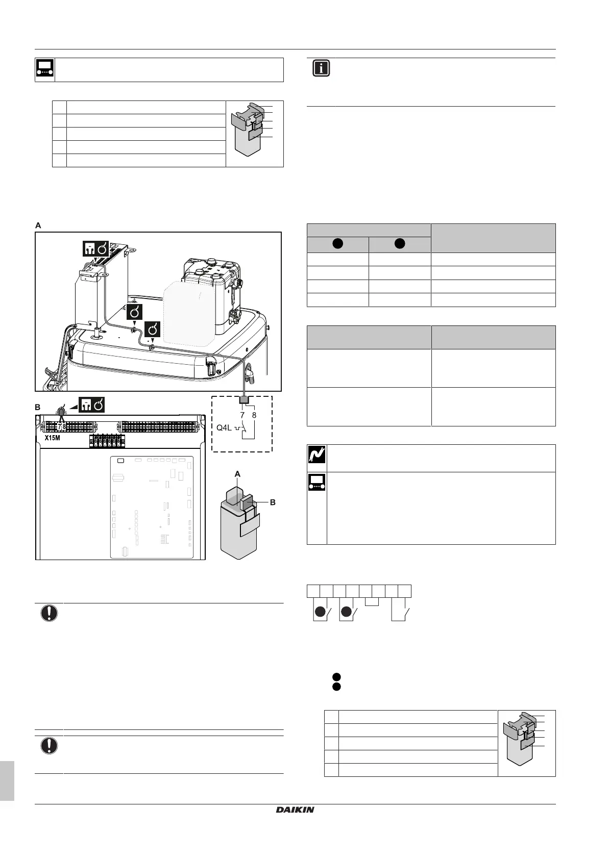
1 Open the following (see "4.2.1To open the indoor unit"[413]):
1 User interface panel
2 Switch box
3 Switch box cover
4 Top cover
5 Side panel
2 Connect the safety thermostat (normally closed) cable to the
appropriate terminals as shown in the illustration below.
Note: The jumper wire (factory-mounted) must be removed from the
respective terminals.
3 Fix the cable with cable ties to the cable tie mountings. General
information, see "6.3.1 To connect the electrical wiring to the
indoor unit"[422].
NOTICE
Make sure to select and install the safety thermostat
according to the applicable legislation.
In any case, to prevent unnecessary tripping of the safety
thermostat, we recommend the following:
▪ The safety thermostat is automatically resettable.
▪ The safety thermostat has a maximum temperature
variation rate of 2°C/min.
▪ There is a minimum distance of 2m between the safety
thermostat and the 3‑way valve.
NOTICE
Error. If you remove the jumper (open circuit) but do NOT
connect the safety thermostat, stop error 8H-03 will occur.
INFORMATION
ALWAYS configure the safety thermostat after it is
installed. Without configuration, the unit will ignore the
safety thermostat contact.
6.3.13 To connect a Smart Grid
This topic describes 2 possible ways to connect the indoor unit to a
Smart Grid:
▪ In case of low voltage Smart Grid contacts
▪ In case of high voltage Smart Grid contacts. This requires the
installation of the Smart Grid relay kit (EKRELSG).
The 2 incoming Smart Grid contacts can activate the following Smart
Grid modes:
Smart Grid contact Smart Grid operation mode
0 0 Free running
0 1 Forced off
1 0 Recommended on
1 1 Forced on
The use of a Smart Grid pulse meter is not mandatory:
If Smart Grid pulse meter is… Then [9.8.8] Limit setting kW
is…
Used
([9.A.2] Electricity meter 2 ≠
None)
Not applicable
Not used
([9.A.2] Electricity meter 2 =
None)
Applicable
In case of low voltage Smart Grid contacts
Wires (Smart Grid pulse meter): 0.5mm²
Wires (low voltage Smart Grid contacts): 0.5mm²
[9.8.4]=3 (Benefit kWh power supply = Smart Grid)
[9.8.5] Smart Grid operation mode
[9.8.6] Allow electrical heaters
[9.8.7] Enable room buffering
[9.8.8] Limit setting kW
The wiring of the Smart Grid in case of low voltage contacts is as
follows:
8
7
S11S
65
S S10
43
X 5M1
S S4
109
a
21
a Jumper (factory-mounted). If you also connect a safety
thermostat (Q4L), replace the jumper with the safety
thermostat wires.
S4S Smart Grid pulse meter
/S10S
Low voltage Smart Grid contact 1
/S11S
Low voltage Smart Grid contact 2
1 Open the following (see "4.2.1To open the indoor unit"[413]):
1 User interface panel
2 Switch box
3 Switch box cover
4 Top cover
5 Side panel
2 Connect the wiring as follows: