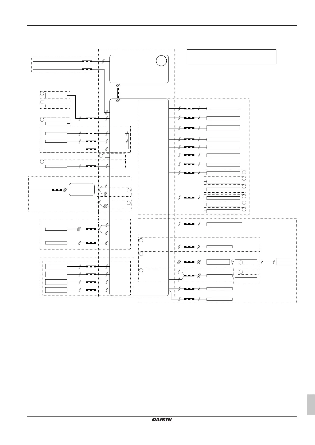
For more details, please check the unit wiring.
Power supply
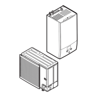
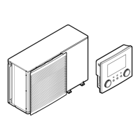
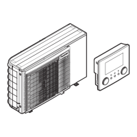
OUTDOOR UNIT
X1M: 1-2-3-earth
4 core
X1M: 1-2-3-earth
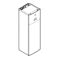
INDOOR UNIT
3 core
indoor unit power supply: 230 V + earth
X1M: 4-5-6
STANDARD PART
Alarm indication
X12M: 1-2
Alarm output
2 core
230 V
2 core
signal
X12M: 3-4
Changeover to
ext. heat source output
Ext. heat source (eg boiler)
NO valve: X12M: 14-18
NC valve: X12M: 13-18
2 core
230 V
2WAY VALVE
M4S for cooling mode
X15M: 11-12
communication
A14P: P1-P2 user interface
Notes:
- In case of signal cable: keep minimum distance to power cables > 5 cm
X12M: 7-8
2 core
230 V
Circulation pump for DHW
X15M: 1-2
2 core
signal
External thermistor (indoor or outdoor)
Only for KRCS01-1 or EKRSCA1
FIELD SUPPLY
2 core
signal
A8P: X801M: 1-5
Power limitation
demand input 1
2 core
signal
A8P: X801M: 2-5
Power limitation
demand input 2
2 core
signal
A8P: X801M: 3-5
Power limitation
demand input 3
2 core
signal
A8P: X801M: 4-5
Power limitation
demand input 4
Only for *KRP1AHTA
OPTIONAL PART
Cooling/heating
On/OFF output
2 core
230 V
X12M: 5-6
Cooling/heating
On/OFF output
Only for remote
user interface
X15M: 3-4
2 core
2x0.75
2 core
2x0.75
X15M: 7-8
X15M: 8
X15M: 7
2
Safety thermostat Q4L
2
1
Smartgrid contact K1A
Smartgrid relais K1A
Smartgrid relais K2A
X12M: 23-25
2 core
2x0.75
X12M: 24-25
2 core
2x0.75
Optional part
Only for HV smartgrid
signal
Only for LV smartgrid
1
Smartgrid contact S10S
FIELD SUPPLY
X15M: 5-6
signal
Electricity meter pulse input 1
2 core
X15M: 9-10
Electricity meter pulse input 2
signal
2 core
Smartgrid pulse meter
5
5
4
Smartgrid contact K2A
4
Only for HV smartgrid
4Only for LV smartgrid
Smartgrid contact S11S
FIELD SUPPLY
Preferential kWh rate
power supply contact
1
FIELD SUPPLY
A20P: J2
(WLAN adapter module)
A11P: X5: 4-5
A11P: X9: 1-2-3
5 core
communication
OPTIONAL PART
3 core
HV smartgrid control supply: 230 V
3 core
A11P: X3: 2-3-4
(BZ mixing kit)
A30P: ST6
communication
Gas meter pulse input
5
2 core
signal
Solar input
X15M: 13-14
2 core
230 V
X12M: 11-12
DHW output
3 core for C/H operation
2 core for H only operation
signal
A2P: X1M: C-com-H
signal
5 core for C/H operation
4 core for H only operation
A15P: X1M: H-C-com
X2M: L-N
signal
2 core
(3m included)
R2T
External sensor
(floor or ambient)
signal
4 core
A3P
Only for *KRTW
(wired room thermostat)
Only for *KRTR
(wireless room thermostat)
Only for
(heat pump convector)
Only for *KRTETS
EXTERNAL ROOM THERMOSTAT / HEAT PUMP CONVECTOR
(main and/or additional zone)
3
3
3
main: X12M: 15-16-22
add: X12M: 19-20-22
main: X12M: 15-16-21-22
add: X12M: 19-20-21-22
main: X12M: 15-22
add: X12M: 19-22
main & add: X12M: 9-10
6
6
only for EKRTR1
only for EKRTRB
A2P: X1M: 1-3
A2P: X1M: 1-2
2 core
2x0.75
communication
A13P: P1-P2 user interface
Only for LAN adapter
X6M: L-N + earth
or L1-L2-L3-N + earth
5 or 3
core
(F1B)
BUH SWB
X33Y: 1-2-3-4
X30Y: 1-2
OPTIONAL PART
7
X33Y: 1-2-3-4-5-6
7
backup heater power supply
(3/6/9 kW):
400 V or 230 V + earth
for 3 kW
for 6 and 9 kW
2 core
2x0.75
outdoor unit power supply: 400 V or 230 V + earth
5 or 3 core
X1M: L1-L2-L3-N-earth or
X1M: L-N-earth
4D132247 D