7 Installation
Installer reference guide
37
ERGA04~08DAV3(A) + EHBH/X04+08DA
Daikin Altherma – Low temperature split
4P496758-1 – 2017.12
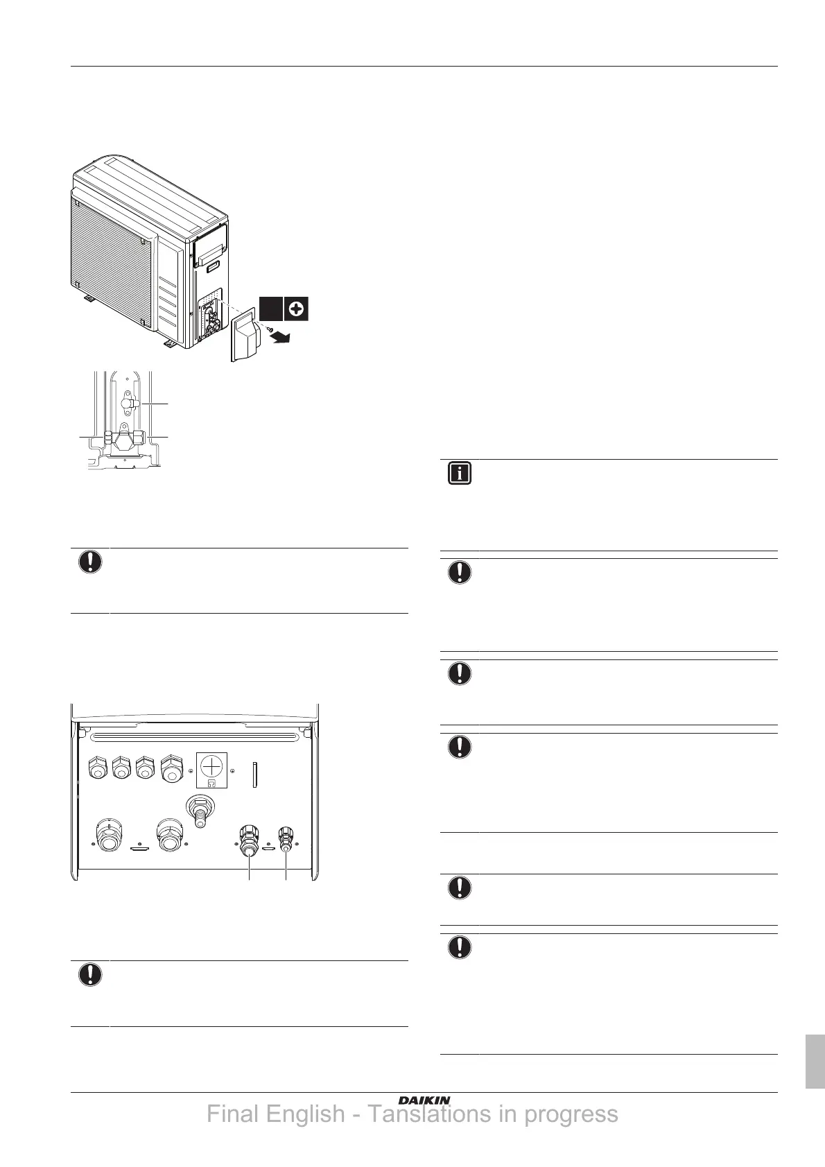
7.5.8 To connect the refrigerant piping to the
outdoor unit
1 Connect the liquid refrigerant connection from the indoor unit to
the liquid stop valve of the outdoor unit.
a Liquid stop valve
b Gas stop valve
c Service port
2 Connect the gas refrigerant connection from the indoor unit to
the gas stop valve of the outdoor unit.
NOTICE
It is recommended that the refrigerant piping between
indoor and outdoor unit is installed in a ducting or the
refrigerant piping is wrapped with finishing tape.
7.5.9 To connect the refrigerant piping to the
indoor unit
1 Connect the liquid stop valve from the outdoor unit to the
refrigerant liquid connection of the indoor unit.
a Refrigerant liquid connection
b Refrigerant gas connection
2 Connect the gas stop valve from the outdoor unit to the
refrigerant gas connection of the indoor unit.
NOTICE
It is recommended that the refrigerant piping between
indoor and outdoor unit is installed in a ducting or the
refrigerant piping is wrapped with finishing tape.
7.6 Checking the refrigerant piping
7.6.1 About checking the refrigerant piping
The outdoor unit's internal refrigerant piping has been factory tested
for leaks. You only have to check the outdoor unit's external
refrigerant piping.
Before checking the refrigerant piping
Make sure the refrigerant piping is connected between the outdoor
unit and the indoor unit.
Typical workflow
Checking the refrigerant piping typically consists of the following
stages:
1 Checking for leaks in the refrigerant piping.
2 Performing vacuum drying to remove all moisture, air or
nitrogen from the refrigerant piping.
If there is a possibility of moisture being present in the refrigerant
piping (for example, water may have entered the piping), first carry
out the vacuum drying procedure below until all moisture has been
removed.
7.6.2 Precautions when checking the
refrigerant piping
INFORMATION
Also read the precautions and requirements in the
following chapters:
▪ General safety precautions
▪ Preparation
NOTICE
Use a 2-stage vacuum pump with a non-return valve that
can evacuate to a gauge pressure of −100.7 kPa
(−1.007 bar)(5 Torr absolute). Make sure the pump oil
does not flow oppositely into the system while the pump is
not working.
NOTICE
Use this vacuum pump for R32 exclusively. Using the
same pump for other refrigerants may damage the pump
and the unit.
NOTICE
▪ Connect the vacuum pump to the service port of the
gas stop valve.
▪ Make sure that the gas stop valve and liquid stop valve
are firmly closed before performing the leak test or
vacuum drying.
7.6.3 To check for leaks
NOTICE
Do NOT exceed the unit's maximum working pressure (see
"PS High" on the unit name plate).
NOTICE
Make sure to use a recommended bubble test solution
from your wholesaler. Do not use soap water, which may
cause cracking of flare nuts (soap water may contain salt,
which absorbs moisture that will freeze when the piping
gets cold), and/or lead to corrosion of flared joints (soap
water may contain ammonia which causes a corrosive
effect between the brass flare nut and the copper flare).
Final English - Tanslations in progress