14 Technical data
Installer reference guide
91
ERGA04~08DAV3(A) + EHBH/X04+08DA
Daikin Altherma – Low temperature split
4P496758-1 – 2017.12
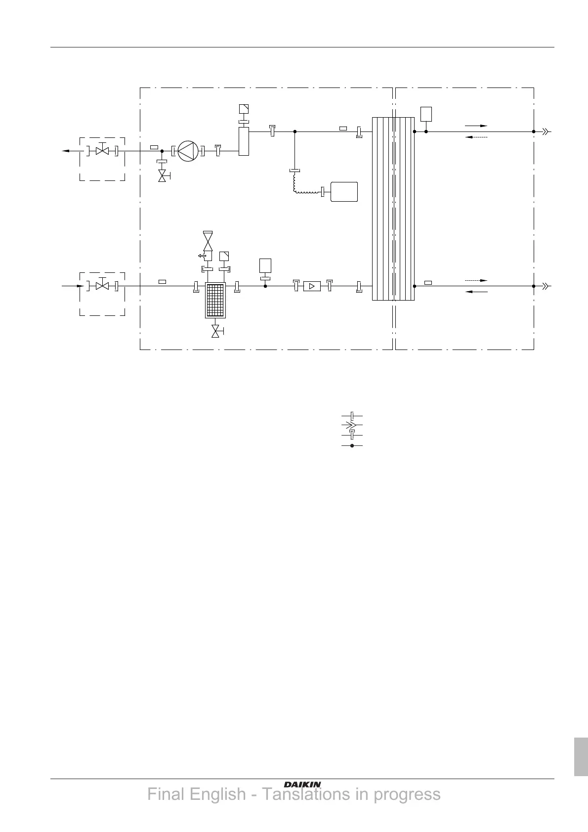
14.2 Piping diagram: Indoor unit
3D111541A
R2T
R4T
B1PW
B2PR
R1T
R3T
A
C
e
e
C
f
i
g
m
a2
a1
h
l
k
d
h
j
c1
b2
c2
b1
B
i
A Water side
B Refrigerant side
C Field installed
a1 Space heating water IN
a2 Space heating water OUT
b1 Gas refrigerant IN (heating mode; condenser)
b2 Liquid refrigerant OUT (heating mode; condenser)
c1 Liquid refrigerant IN (cooling mode; evaporator)
c2 Gas refrigerant OUT (cooling mode; evaporator)
d Plate heat exchanger
e Shut-off valve for service
f Magnetic filter/dirt separator
g Safety valve
h Air purge
i Drain valve
j Flow sensor
k Expansion vessel
l Backup heater
m Pump
B1PW Space heating water pressure sensor
B2PR Refrigerant pressure sensor
R1T Thermistor (heat exchanger – water OUT)
R2T Thermistor (backup heater – water OUT)
R3T Thermistor (liquid refrigerant)
R4T Thermistor (heat exchanger – water IN)
Screw connection
Flare connection
Quick coupling
Brazed connection
Final English - Tanslations in progress