installation Considerations
www.DaikinApplied.com 5 LARGE VERTICAL WSHP IM 1059-12
Unit location
Large Vertical Water Source Heat Pump units are easily
located in equipment rooms or oor-by-oor installations.
They can be applied to all building types where it is
advantageous to extend the water source heat pump
concept to larger or core areas.
Locate the unit in an area that allows for easy removal
of the lter and access panels, and has enough space
for service personnel to perform maintenance or repair.
Provide sufcient room to make water, electrical and
duct connections.
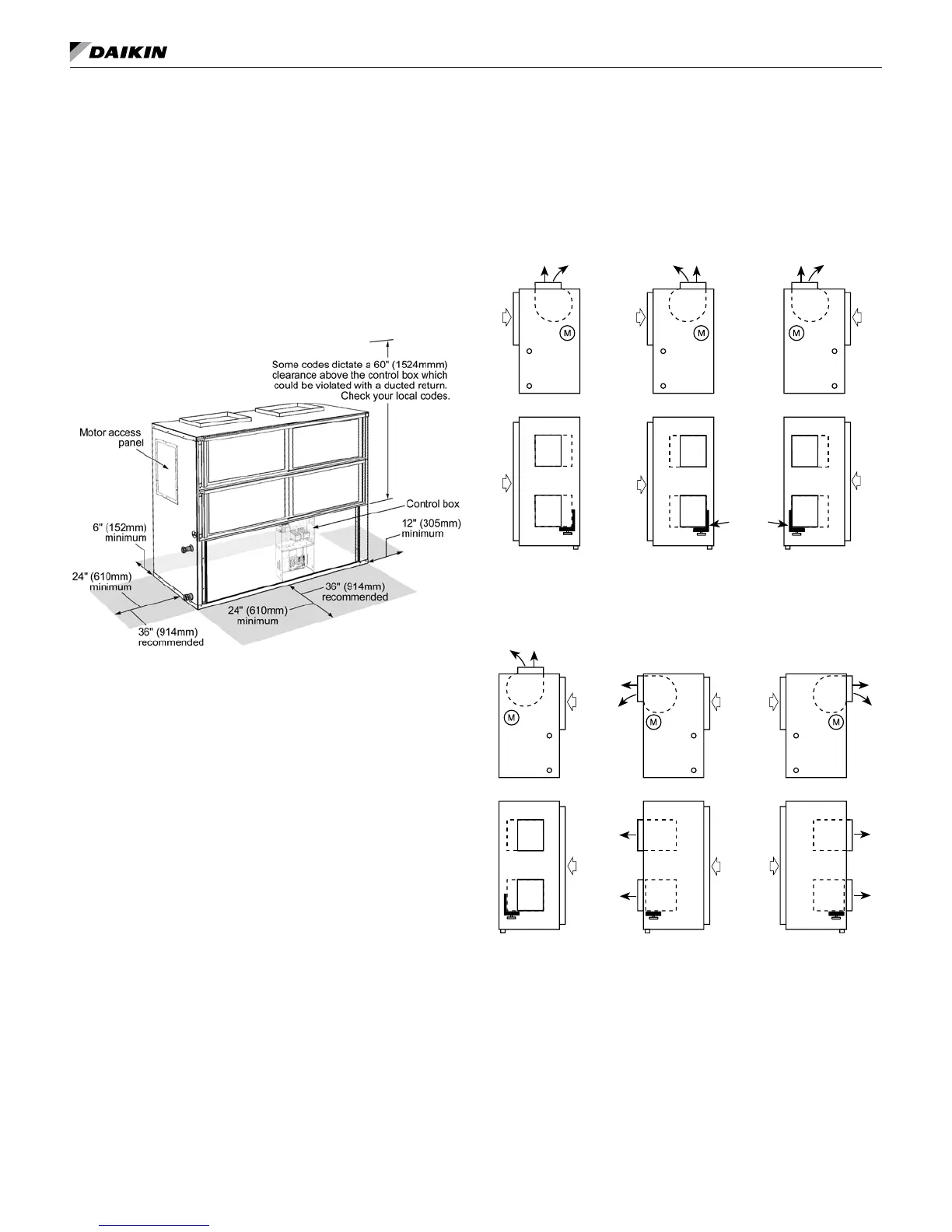
Figure 1: Service clearances
Notes 1. A 12" (305 mm) minimum clearance is re-
quired on the side opposite the pipe connec-
tion side to gain access to panel to remove
locking collar for shaft removal.
2. Top clearance is required for fan shaft removal.
The contractor should make sure that access has been
provided including clearance for 2" (51 mm) thick lter
brackets, duct collars and ttings at water and electrical
connections. Allow adequate room around the unit
for a condensate trap. The unit can be installed “free
standing” in an equipment room. Generally, the unit is
located in a separate room with the non-ducted return air
facing the return air intake.
Alternatively, the unit can have a ducted return air. It is
recommended that the unit be located on vibration isolators
to reduce any vibration (see Figure 3 on page 6).
Fan deck arrangements
Six fan discharge arrangements and two piping
arrangements are available. With the return air side
dened as the “front” of the unit, the water piping
connections may be right-hand (side) or left-hand. All units
have a single supply and return water connection with
a copper FPT type tting that protrudes through the unit
casing for easy connection. The condensate connection is
also a copper FPT type and is located on both sides of the
unit. The unused connection is plugged.
The main control panel is located in the center front of
the unit. The fan discharge is top front, and the fan motor
is always located at the piping end. Unit sides opposite
the control panel and opposite the piping side may be up
against walls and still allow for service and maintenance
through the remaining access panels.
Figure 2: Fan deck arrangements
Fan
Motor
Rear (or Top)
Discharge
Right-Hand Piping
(Upblast-Rear)
Front (or Top)
Discharge
Right-Hand Piping
(Upblast-Front)
Front (or Top)
Discharge
Left-Hand Piping
(Upblast-Front)
Rear (or Top)
Discharge
Left-Hand Piping
(Upblast & Rear)
Straight Horizontal
Discharge Left-Hand
Piping (Top-Horizontal
Discharge)
Straight Horizontal
Discharge Right-Hand
Piping (Top-Horizontal
Discharge)
Notes: 1. The hand of unit is determined by looking
at the return air (lter) side. The piping and
electrical connections are always made on
the “hand” side of the unit. The return air (l-
ter) side is considered the “front” of the unit.
2. The fan motor is always located at the piping/
electrical connection (hand) side of the unit.