unit installation
www.DaikinApplied.com 22 LARGE VERTICAL WSHP IM 1059-12
Environment
This equipment is designed for indoor installation
only. Sheltered locations such as attics, garages, etc.,
generally will not provide sufcient protection against
extremes in temperature and/or humidity, and equipment
performance, reliability, and service life may be
adversely affected.
Power supply
A voltage variation of +/-10% of nameplate voltage is
acceptable. Three-phase system imbalance shall not
exceed 2%.
Electrical data
General
1. Verify the compatibility between the voltage and
phase of the available power and that shown on the
unit serial plate. Line and low voltage wiring must
comply with local codes or the National Electrical
Code, whichever applies.
2. Apply correct line voltage to the unit. A 7⁄8" (22mm)
hole and/or a 1-1⁄8" (29 mm) knockout is supplied
on the side of the unit. A disconnect switch near the
unit is required by code. Power to the unit must be
sized correctly and have dual element (Class RK5)
fuses or an HACR circuit breaker for branch circuit
over-current protection. See the nameplate for
correct ratings.
3. Three phase 50 cycle units require a neutral wire for
230/50-1 power to the fan circuit.
4. Connect the thermostat/subbase wiring with the
power “off ” to the unit.
5. Field supplied relays installed on the input terminals
W1, W2, Y1, Y2 or G may introduce electrical noise.
Never install relay coils in series with the inputs.
Operating voltages
208/230-60-1 ...............197 volts min.; 253 volts max.
265-60-1 ......................238 volts min.; 292 volts max.
230-50-1 ......................197 volts min.; 253 volts max.
460-60-3 ......................414 volts min.; 506 volts max.
575-60-3 ......................515 volts min.; 632 volts max.
Note: Voltages listed are to show voltage range. However,
units operating with over-voltage and under-voltage
for extended periods of time will experience premature
component failure. Three phase system unbalance
should not exceed 2%.
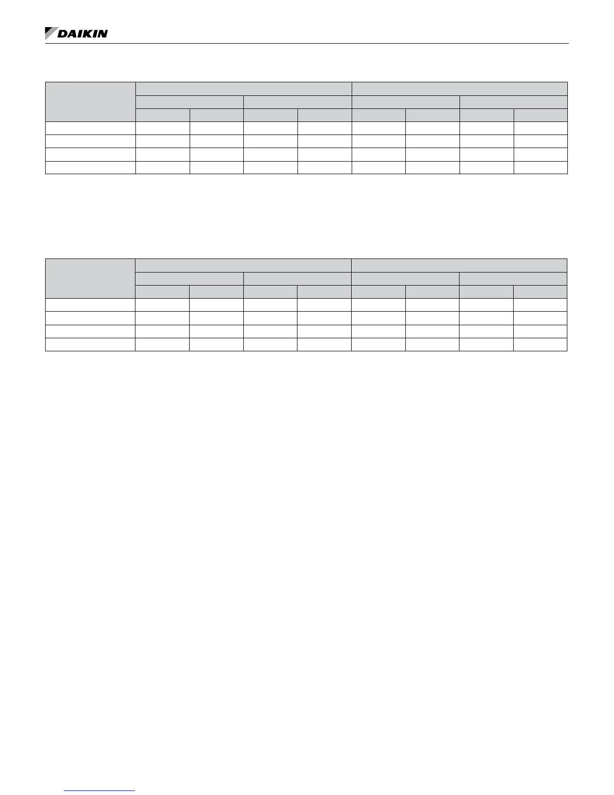
Table 4: Water source heat pump operating temperature limits (for continuous duty)
Operating Mode
Entering Air °F Entering Water °F
Minimum Maximum Standard Range Extended Range
DB WB DB WB Minimum Maximum Minimum Maximum
Cooling 65 55 85 71 55 110 50 110
Ambient 50 – 100 – – – – –
Heating 50 – 80 – 55 90 20 90
Ambient 50 – 85 – – – – –
Notes: 1. In the heating mode, the sum of the entering air + entering water must be ≥ 100°F.
2. MINIMUM WATER FLOW = 1.5 GPM/Ton.
3. Maximum and minimum values may not be combined. If one value is at maximum or minimum, the other two conditions
may not exceed the normal condition for standard units. Extended range units may combine any two maximum
conditions, but not more than two, with all other conditions being normal conditions.
Table 5: Water source heat pump operating temperature limits at start-up (not for continuous duty)
Operating Mode
Entering Air °F Entering Water °F
Minimum Maximum Standard Range Extended Range
DB WB DB WB Minimum Maximum Minimum Maximum
Cooling 50 40 105 87 45 120 30 120
Ambient 45 – 110 – – – – –
Heating 40 – 85 – 40 95 20 100
Ambient 40 – 85 – – – – –