start-uP
www.DaikinApplied.com 24 LARGE VERTICAL WSHP IM 1059-12
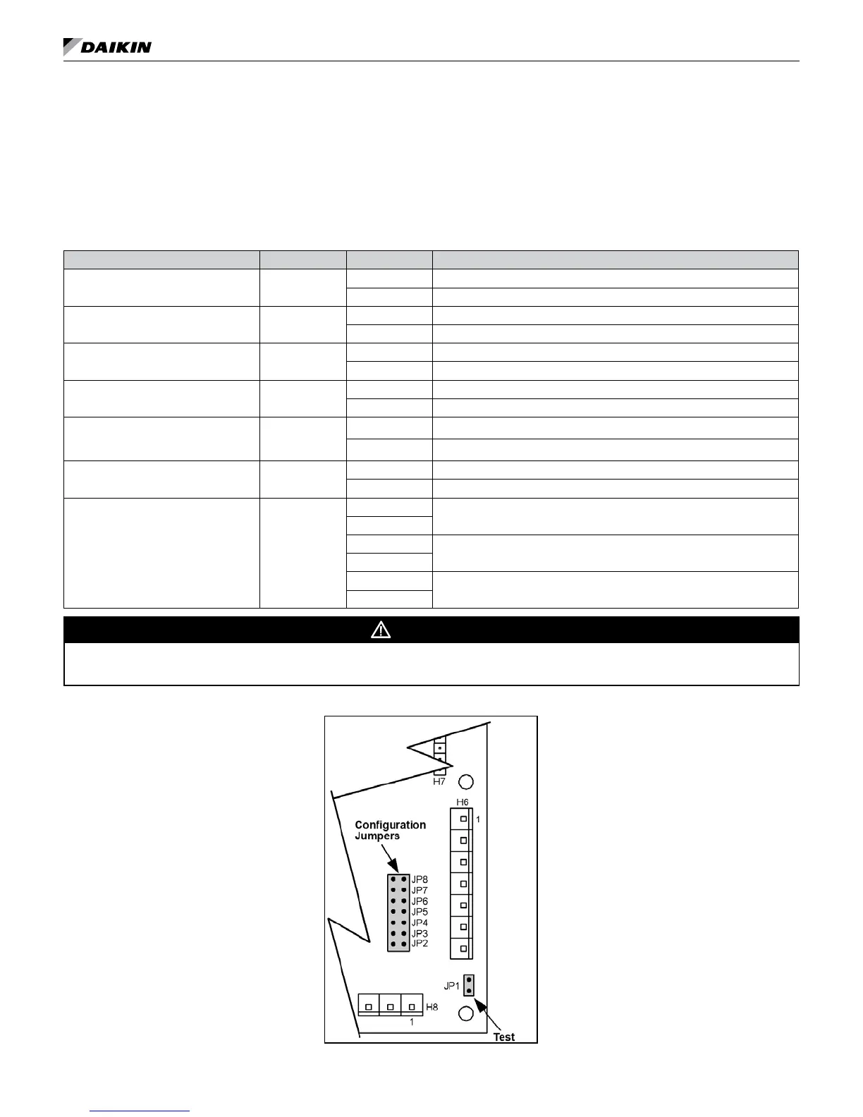
Note: The settings of the hardware conguration jumpers are read when the controller is powered. Any changes to
the jumper settings require cycling power to the controller or sending a controller a reboot command through
the network communications.
Table 10: MicroTech III controller configuration jumper settings
Baseboard Description Jumper(s) Jumper Setting Function
Normal / Test Mode JP1
Open Normal Operation
Shorted Service / Test Mode
Fan Operation JP2
Open Continuous Fan Operation (On), when not operating in the unoccupied mode.
Shorted Cycling Fan Operation (Auto)
Loop Fluid
JP3
(see warning)
Open Water Loop Fluid - Water freeze protection (factory default setting)
Shorted Glycol Loop Fluid - Systems with anti-freeze protection
Freeze Fault Protection JP4
Open None
Shorted Freeze fault protection enabled
Room Sensor Setpoint
Potentiometer Range
JP5
Open Short Range: -5 to +5 ºF (-2.78 to +2.78 ºC)
Shorted Long Range: 55 to 95ºF (12.78 to 35ºC)
Thermostat / Room Sensor JP6
Open Thermostat Control
Shorted Room Sensor Control
Compressor Availability JP7 & JP8
JP7 Open
Both Compressors Available (default)
JP8 Open
JP7 Shorted
One Compressor Available
JP8 Open
JP7 Open
No Compressors Available
JP8 Shorted
WARNING
Jumper JP3 is factory provided in the open position. Extended range units require freeze protection down to 15 degrees. Jumper JP3 must
be eld congured.
Figure 16: Location of configuration jumpers on the MicroTech III unit controller
Start-up
1. Open all valves to full open position and turn on
power to the conditioner.
2. Jumpers must be congured prior to connecting
supply power. See Table 10 and Table 11 on page
25.