www.DaikinApplied.com 13 LARGE VERTICAL WSHP IM 1059-12
unit installation
Condensate Drain Connection
A eld provided condensate trap must be installed on
each water source heat pump. Condensate removal
piping must be pitched away from the unit not less than
1/4" per foot. The vent should extend at least 1-1/4"
above the unit condensate tting. A vent is required after
the trap so that the condensate will drain away from
the unit. The vent can also act as a clean out if the trap
becomes clogged. To avoid having waste gases entering
the building, the condensate drain should not be directly
piped to a drain/waste/vent stack. See local codes for
the correct application of condensate piping to drains
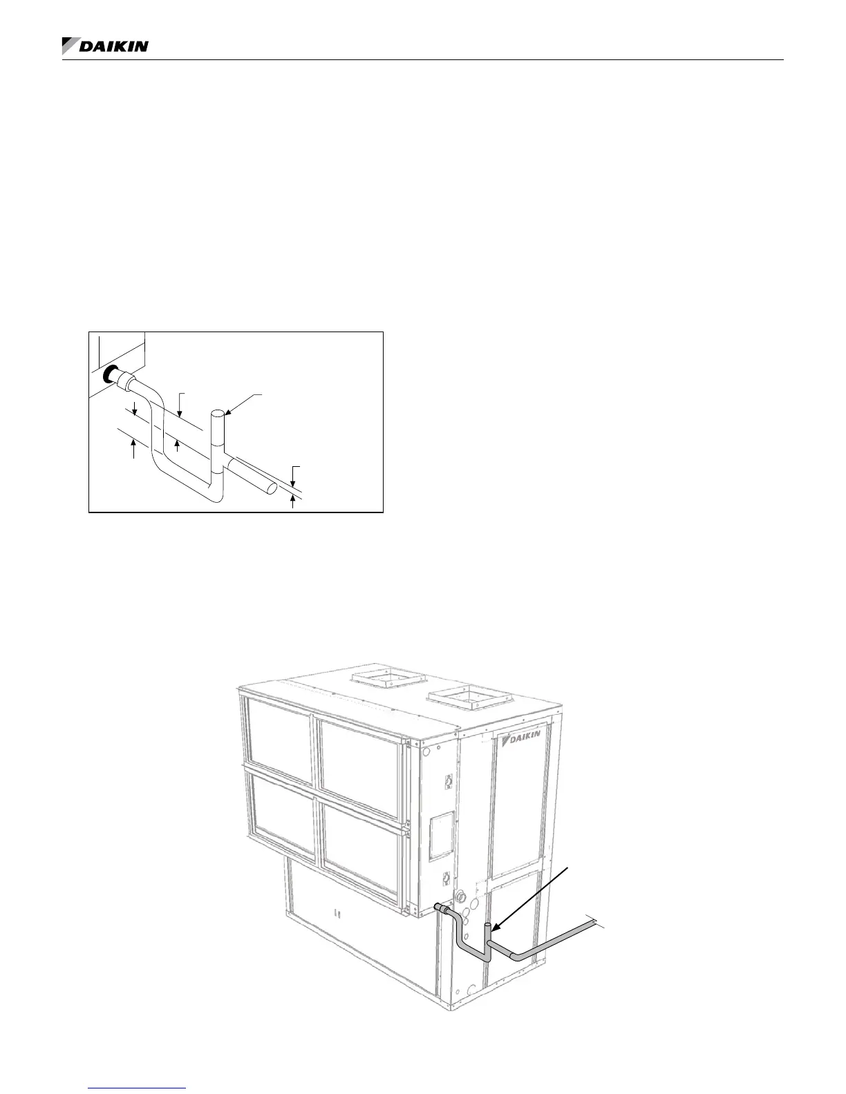
Figure 13: Unit condensate drain pipe trap detail
Optional
Field- Installed Vent
1-1⁄2"
(38mm)
1-1⁄2" (38mm)
1⁄4" Per Foot
(21mm Per Meter)
Note: Improper trapping can lead to several problems. If
the trap is too tall, negative pressure will prevent
drainage, causing condensate backup. If the trap is
too short the seal will be destroyed or nonexistent,
producing the same effect as a non-trapped system.
1. Each water source heat pump is provided with
a 3/4" FPT ush mount tting for connection of
a condensate drain. A complete copper or PVC
condensate system can be used. Copper or steel
condensate piping should be insulated to prevent
sweating. In most applications the use of PVC
prevents sweating of condensate drain.
2. Do not locate any point in the drain system above
the condensate drain connection of any unit.
It may be necessary to manually ll the trap at system
startup, or to run the unit for sufcient time to build a
condensate seal. The condensate trap and condensate
piping drainage should be free of any foreign debris.
Debris can prevent proper drainage and unit operation
and result in condensate buildup.
3. Do not locate any point in the drain system above
the drain connection of any unit.
4. Automatic ow controlled devices must not be
installed prior to system cleaning and ushing.
5. A high point of the piping system must be vented.
6. Check local code for the need for dielectric ttings.
Figure 14: WSE condensate drain pipe detail
Vent