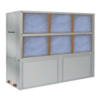
start-uP
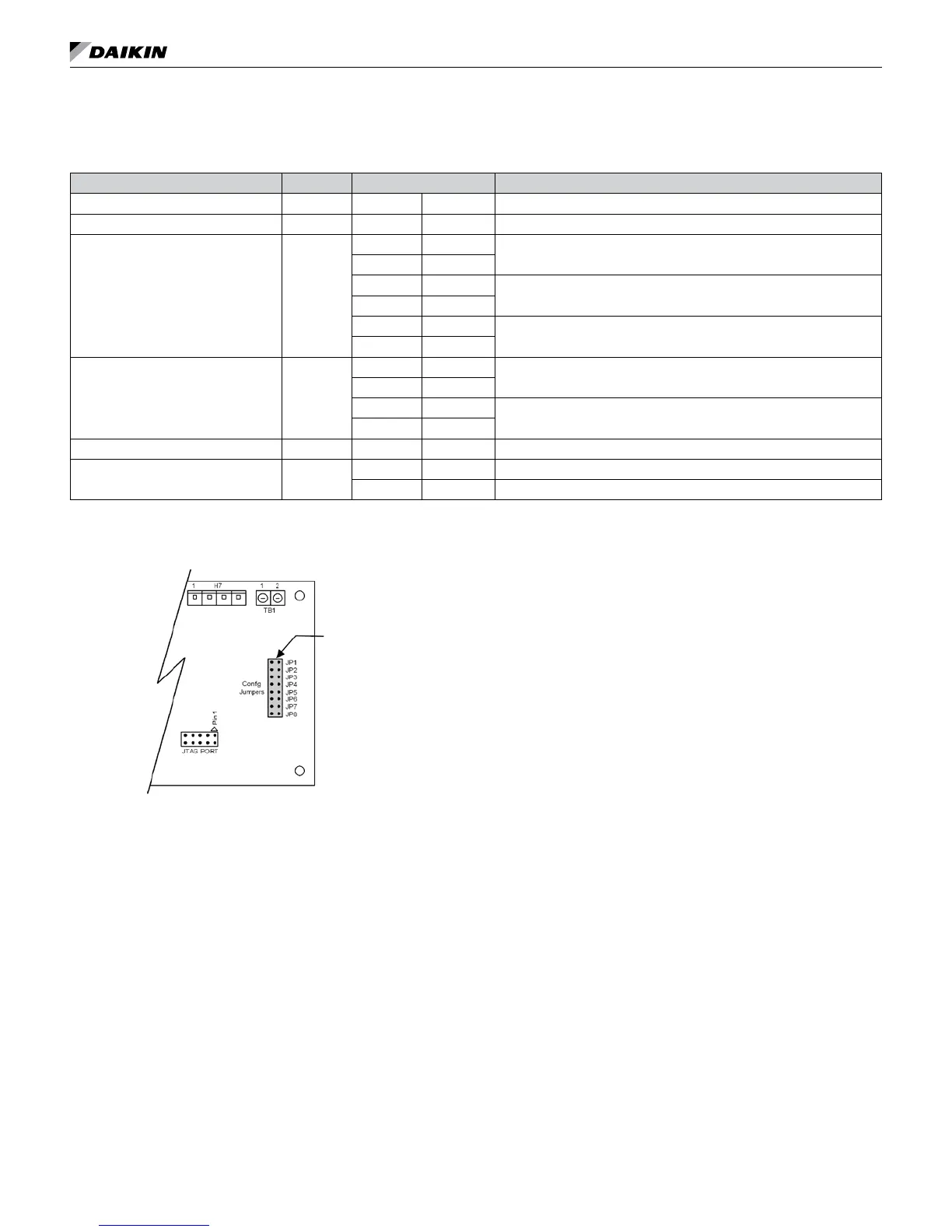
Note: The settings of the hardware conguration jumpers are read when the controller is powered. Any changes to the jumper settings
require cycling power to the controller or sending a controller a reboot command through the network communications.
Table 11: I/O expansion module jumper settings
I/O Expansion Description Jumper(s) Jumper Setting Model
Not Used JP1 JP1 Open
–
Not Used JP2 JP2 Open
–
Secondary Heating
Options
JP3 & JP4
JP3 Open
None
JP4 Open
JP3 Shorted
Supplemental Electric Heat
JP4 Open
JP3 Open
Boilerless Electric Heat
JP4 Shorted
Cooling / Dehumidication
Options
JP5 & JP6
JP5 Shorted
Without Hydronic Cooling
JP6 Open
JP5 Open
Hydronic Cooling (Waterside Economizer)
JP6 Shorted
Not Used JP7 JP7 Open –
Lead Compressor Option JP8
JP8 Open Compressor #1 is Lead (factory default setting)
JP8 Shorted Compressor #2 is Lead
IM 1059-12 LARGE VERTICAL WSHP 25 www.DaikinApplied.com
Figure 17: I/O expansion module configuration jumper
terminals
Jumper Terminals
3. Set thermostat to “Cool”. If the thermostat is an
automatic changeover type, simply set the cooling
temperature to the coolest position. On manual
changeover types additionally, select “Cool” at the
system switch.
Again, many conditioners have time delays which
protect the compressor(s) against short cycling.
After a few minutes of operation, check the
discharge grilles for cool air delivery. Measure
the temperature difference between entering and
leaving water. It should be approximately 1½
times greater than the heating mode temperature
difference. For example, if the cooling temperature
difference is 15°F (8°C), the heating temperature
difference should have been 10°F (5°C).
Without automatic ow control valves, target a
cooling temperature difference of 10°F to 14°F (5°C
to 8°C). Adjust the combination shutoff/balancing
valve in the return line to a water ow rate which will
result in the 10˚F to 14°F (5°C to 8°C) difference.
4. Set thermostat to “Heat.” If the thermostat is the
automatic changeover type, set system switch to the
“Auto” position and depress the heat setting to the
warmest selection. Some conditioners have built-in time
delays which prevent the compressor from immediately
starting. With most control schemes, the fan will
start immediately. After a few minutes of compressor
operation, check for warm air delivery at discharge
grille. If this is a “cold building” start-up, leave unit
running until return air to the unit is at least 65°F (18°C).
Measure the temperature difference between
entering and leaving air and entering and leaving
water. With entering water of 60°F to 80°F (16°C to
27°C), leaving water should be 6°F to 12°F (3.3°C
to 6.6°C) cooler (under full load conditions) and the
air temperature rise through the machine should not
exceed 35°F (19°C). If the air temperature exceeds
35°F (19°C), then the water ow rate is inadequate.
5. Check the elevation and cleanliness of the
condensate line. If the air is too dry for sufcient
dehumidication, slowly pour enough water into the
condensate pan to ensure proper drainage.
6. If the conditioner does not operate, check the
following points:
a. Is supply voltage to the machine compatible?
b. Is thermostat type appropriate?
c. Is thermostat wiring correct?