Installation and operation manual
5
FWEC2
Advanced electronic controller
FC66002764
AVAILABLE CONFIGURATIONS (PARAMETER P00)
036
■ System pipes: 4
■ Valve: 2-3 WAYS
■ Electrical heater: NO
■ Fan speed: 4
■ Summer/winter switching logic: AUTOMATIC AIR SIDE
037
■ System pipes: 4
■ Valve: NO
■ Electrical heater: YES
■ Fan speed: 3
■ Summer/winter switching logic: LOCAL MANUAL
038
■ System pipes: 4
■ Valve: NO
■ Electrical heater: YES
■ Fan speed: 4
■ Summer/winter switching logic: LOCAL MANUAL
SERIAL COMMUNICATION
Connection to the RS485 communication network
The communication network (bus type) relies on a simple
shielded 2-conductor cable, directly connected to the RS485
serial ports of the controllers (terminals A, B and GND).
“For the network use a cable AWG 24 (diam. 0.511 mm)”
The communication network must have the following general
structure (fi gure 4).
In the case of the “MASTER-SLAVE” solution a termination
resistor will have to be installed on both controllers at the
furthest ends of the network.
N.B.: (1) Comply with the polarity of the connection: indi-
cated with A(-) and B(+)
(2) Ground shield at one end only
____________________________________________________________
W
ARNING
:
■ Use a shielded cable AWG24
■ Colours suggested for the communication
network: A (-) Brown ; B (+) Yellow
____________________________________________________________
LOGICS
COOLING/HEATING SWITCHING
Four logics are present to select the thermostat operating
modes according to the controller confi guration setting:
1. Local: user choice made through the key
2. Distance: depending on the Digital Input DI1 status (contact
logic: see confi guration parameters of board)
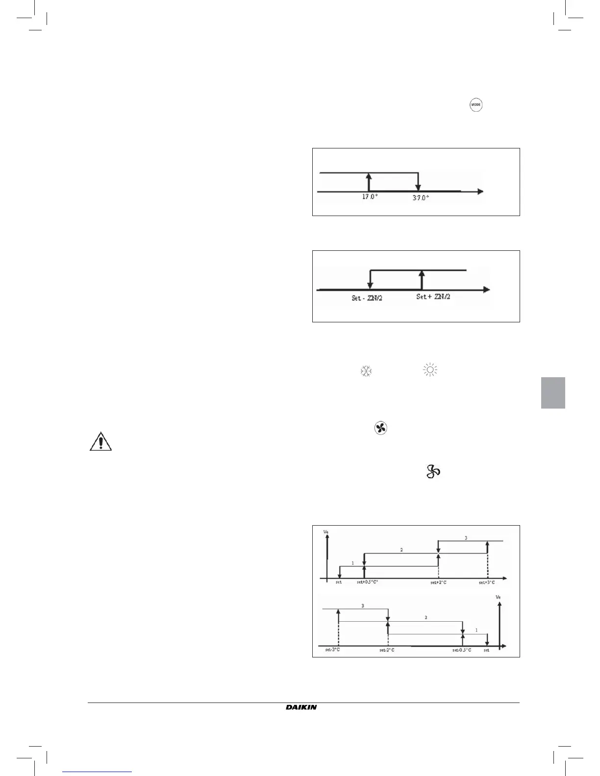
3. Depending on water temperature
N.B.: in case of water sensor alarm, the controller returns
to the Local mode temporarily.
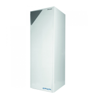
4. depending on air temperature
Where:
■ Set is the temperature setting made by the arrows
■ ZN is the neutral zone (parameter P03)
The thermostat operating mode is indicated on the display by
the symbols
(cooling) and (heating)
FAN SPEED CONTROL
The controller can govern 3 or 4-speed indoor units
OPERATING SPEED SELECTION
Using Fan key
it is possible to select the following
speeds:
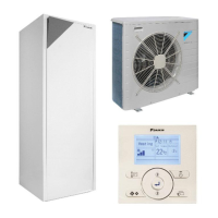
■ Automatic ventilation: depending on the set temperature
and the room air temperature
With 3-speed confi gurations :
where:
1 = low speed
2 = medium speed
3 = maximum speed
Summer
Winter
Air temp.
Summer
Winter
Water temp.
COOLING
HEATING