Installation and operation manual
12
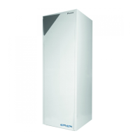
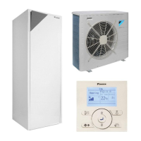
FWEC2
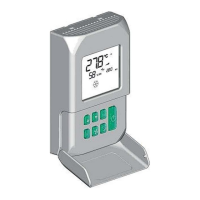
Advanced electronic controller
FC66002764
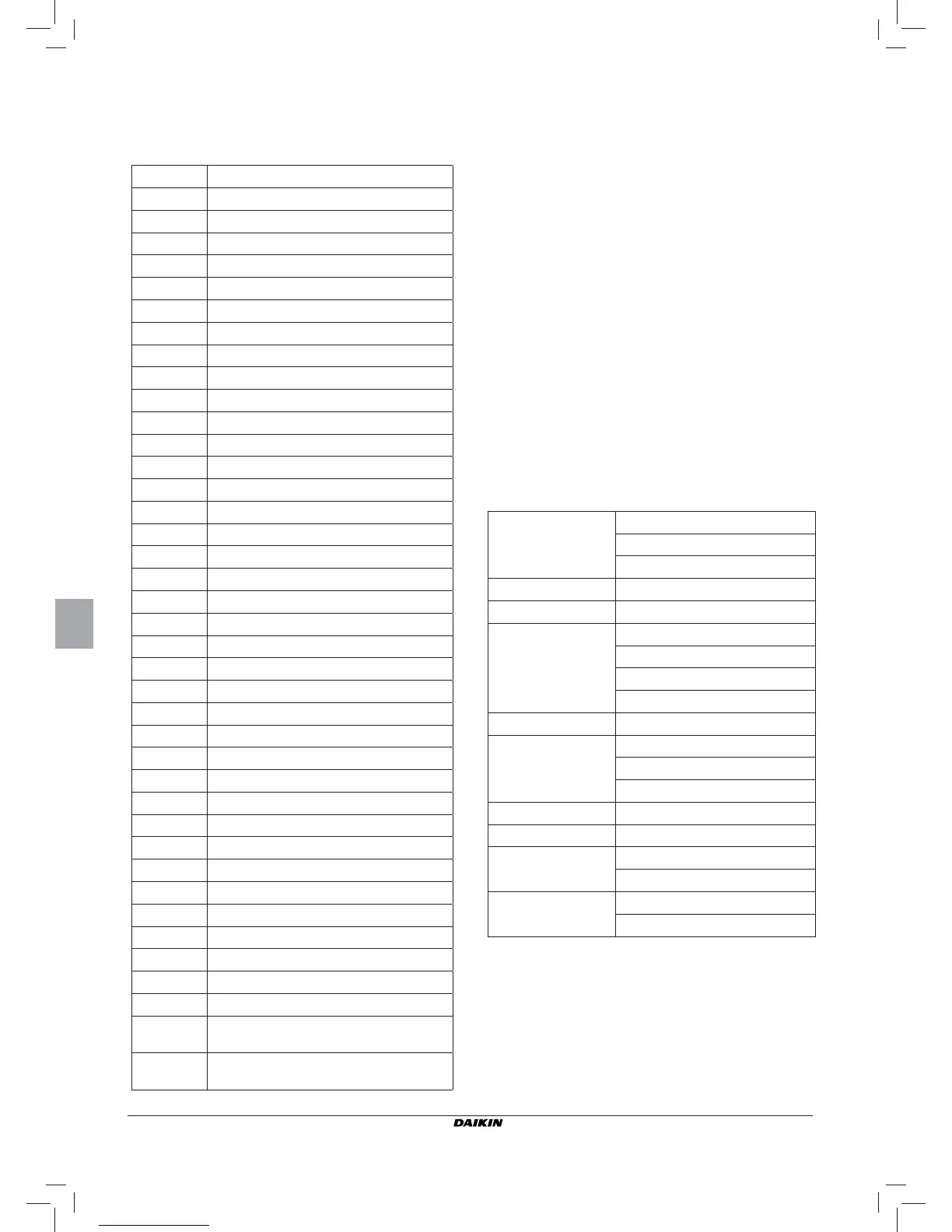
WIRING DIAGRAMS
Key to symbols used in wiring diagrams:
Vo
Extra low speed
V1
Min. speed
V2
Med. speed
V3
Max. speed
L
Phase
PE
Ground
N
Neutral
RE
Electrical heater
SW
Water sensor
SA
Air sensor
SU
Humidity sensor
BK
Black (Max. speed)
BU
Blue (Med. speed)
RD
Red (Extra low speed)
WH
White (common)
GY
Grey
BN
Brown (Min. speed)
GN
Green
YE
Yellow
MS
Flap microswitch
DI1
Digital 1 input
DI2
Digital 2 input
CI2
Digital input common
A/B/GND
RS 485
F
Fuse (not supplied)
IL
Circuit breaker (not supplied)
CN
Terminal board
RHC
Heating/Cooling remote selecting switch
EXT
Remote ON/OFF contact
EPIMB6
Circuit board to control 4 indoor units
EPIB6
Circuit board for FWD units
M
Fan motor
VHC
Solenoid valve –Cool/Heat.
VC
Solenoid valve - Cooling
VH
Solenoid valve - Heating
TSA
Automatic safety thermostat
TSM
Safety fuse
SC
Wiring box
.....
Electrical connections to be made by
installer
ECONOMY
COMFORT / ECONOMY remote selecting
switch
INSTALLATION OF WALL-MOUNTED CONTROLLER
NB: for wall mounting of the controller it is advisable to use
an electric box behind the controller to accommodate
the cables.
NB: Prior to installation, carefully remove the protective fi lm
from the display; removal of the fi lm may cause some
dark streaks to appear on the display but these will
disappear after a few seconds and are not signs of a
controller defect.
INSTRUCTIONS FOR WALL MOUNTING
1. Remove the fastening screw of the controller (FIGURE 8).
2. If a 503 electrical enclosure is used, pass the cables through
the slot at the bottom of the controller and use the holes
provided for fastening.
3. Otherwise, in the wall where you wish to mount the control-
ler, drill holes to match up with the fastening slots (5x8mm)
on the base of the controller; pass the cables through the
slot on the base and screw it to the wall (previously drilled)
(FIGURE 9).
4. Make the electrical connections to the indoor unit terminal
block as per the wiring diagram.
5. Close the controller box and fi x with the screw removed as
described at point 1.
TECHNICAL DATA
Power supply
90-250Vac 50/60Hz
Electrical input 8W
Protection fuse 500mA delayed
Operating temp. Range 0-50°C
Storage temp. Range -10-60°C
Relay
NO 5A @ 240V (Resistive)
insulation: coil-contact distance 8 mm
4000V coil-relay dielectric
Max ambient temperature 105°C
Connectors 250V 10A
Digital inputs
Clean contact
Closing current 2mA
Max. closing resistance 50 Ohm
Analog inputs Temperature and relative humidity probes
Power outputs Relay (see above)
Temperature sensors
NTC sensors 10K Ohm @25°C
Range -25-100°C
Humidity probe
Resistive-type probe
Range 20-90%RH