4-17
4.8.5 I/O Board
●Replacement procedure
1. Removing I/O board
1) Remove the cable that connects to I/O board
from the connector.
2) Remove the mounting bolts on the top and
bottom of I/O board and pull the board
forward.
2. Mounting I/O board
Reverse the above procedure to install I/O board
using two bolts and connect the cable.
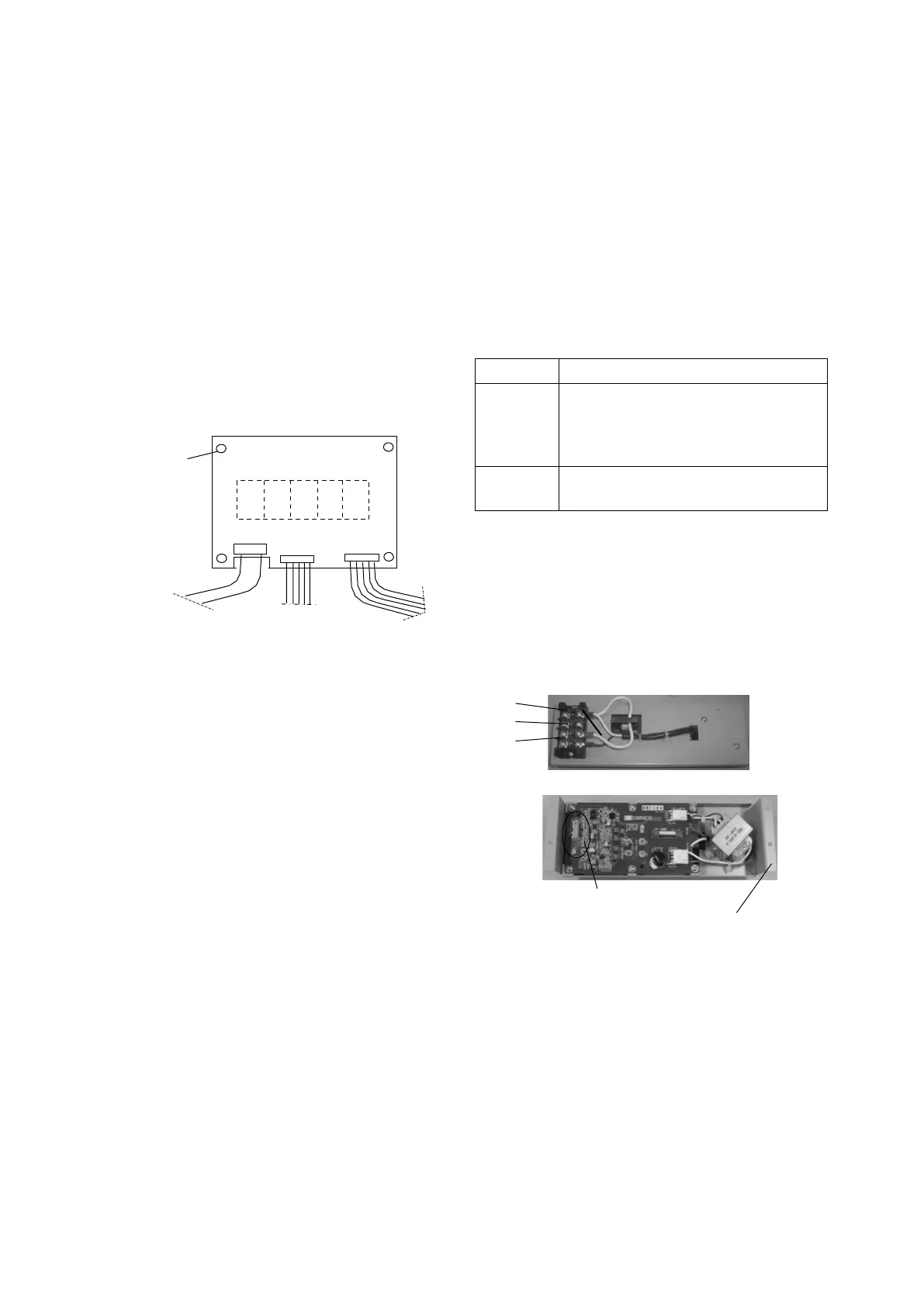
4.8.6 Operation Board
Mounting bolt
×4
X43A
X42A
X41A
●Replacement procedure
1. Removing operation board
1) Remove the three cables that connect to
operation board from the connector.
2) Remove the four mounting bolts.
2. Mounting operation board
Reverse the above procedure to mount operation
board using the four bolts and connect the cable.
3. Necessity for configuration setting
Case 1: When using operation board from Daikin
spare parts, configuration setting is not
required.
Configuration setting for operation
board from spare parts is not made
but that memorized on CPU board is
automatically sent to LED board when
power is supplied.
Case 2: When occasionally using operation
board of the adjacent reefer occasionally,
configuration setting is required.
In this case, ※12 Configuration Set in
paragraph 2.3 is displayed when power
is supplied.
Configuration set points varies by model.
Please refer to "Initial Setting Table"
issued separately.
4.8.7 PT/CT Board
This printed circuit board incorporates the two
functions as a measuring instrument and protective
device and serves as an interface between the
main circuit (high voltage) and controller.
●Function
Function Description
Voltage
and phase
sequence
detection
Voltage and phase sequence
detection between R phase and S
phase is executed by transferring the
voltage waveform to the controller.
Current
detection
Total running current of EFM and
CFM are detected.
●Replacement procedure
①Loosen the four mounting bolts.
② After replacing the main body, mount the
connector by following the original procedure.
③ After checking the connections thoroughly, carry
out test operation to confirm that no abnormality
is present.
T
S
R
Mounting hole (4 pcs.)
Connector X61A
 Loading...