1-10
1.3.8 Printed Circuit Board
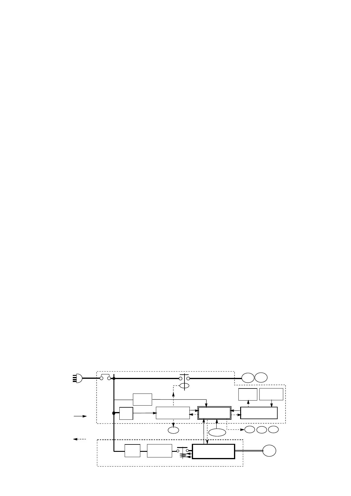
●CPU Board(EC1)
Controller described in this manual means CPU
board. CPU board equips micro-computer and
controls unit with operation software installed.
All information required for the control is input to
the CPU board.
① Sensor information (temperature, humidity,
pressure) and power information (voltage, phase
sequence, current) are input.
② Configuration items (factory set) in accordance
with requirement for individual user's order are
input.
③ For example Unit ON/OFF, SP change, etc are
inputted by key operation.
In responding to these inputs, CPU board outputs
commands to each part to operate unit with
accuracy.
① to modulation valves, solenoid valves and
magnetic contactors
② to inverter board
③ to LCD display
Operation data is stored for 2 years (Logging
interval 60 minutes). The data can be down-loaded
with USB memory or PC installed DCCS software.
When commercial power OFF, some of setting work
and data confirmation can be available by wake-
up battery power (Rechargeable battery). Data
download and software upload are possible. (Refer
battery mode in paragraph 2.3)
Use Daikin spare parts for CPU board replacement.
After replacement, configuration items are
transmitted from operation board. Set controller
time in accordance with setting request displayed
on LCD. Install the latest operation software down-
loaded from web site.
●I/O Board(EC2)
I/O board converts AC24V power from control
transformer Tr1 to DC13V/DC5V and relays it to
CPU board.
I/O board energizes magnetic contactors for fan
motor EFM, CFM and phase correction contactor
PCC1 or 2 by receiving order from CPU board.
At the same time, LED lamps wired in parallel
with them are energized and lighted ON. That is
convenience with service work.
●Operation Board(EC3)
Operation board receives input from keyboard and
transmits it to LCD board and CPU board. On the
other hand it transmits signals from CPU board to
LCD board.
If communication between operation board and
CPU board is failed, operation board judges to
display "Communication Interrupted" on LCD and
CPU board logs alarm E903.
Configuration items factory set to CPU board have
been copied to operation board. When CPU board
is replaced, these items is transmitted to CPU
board.
●Inverter Board(EC8)
Inverter board changes frequency of power source
and controls compressor speed. Inverter board
receives command of revolution number from CPU
board. The operating condition during inverter
control (compressor overload, power supply
condition and actual frequency etc.) are transmitted
to CPU board. The judging of operation continuing
and stopping is conducted by CPU board.
Frequency change is made of frequent switching
control with diode bridge circuit and results high
temperature. Cooling fan circulates air inside
inverter box and cooling fin constructed outside the
box.
CFM EFM
PT/CT
EC7
Operation board
EC3
Inverter box
Control box
C/B
Compressor
AC24V
3 phase AC
380-415V/50Hz
440-460V/60Hz
CM
Inverter board
EC8
ACL
Noise filter
board EC9
MC
Sheet key
EC6
LCD
EC4
I/O board
EC2
CPU board
EC1
Tr
Fan motors
SV
EEV MEV DMV
Sensors
Modulation Valves
Solenoid Valves
Input to
CPU board
Output from
CPU board
AC⇒DC⇒Quasi-AC
Quasi-AC
 Loading...