Daikin IM 696-4 15
Field Wiring
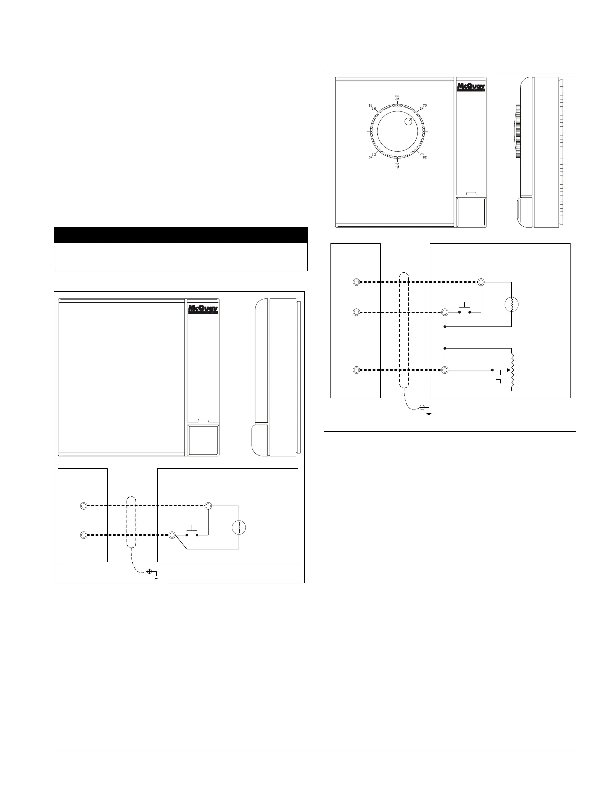
Zone Sensor with Remote Set Point Adjustment
The standard MicroTech II room temperature sensor package
equipped with a set point adjustment potentiometer is available
to use with CAV-ZTC (SCC) units. This sensor package also
includes a tenant override button. The set point adjustment
potentiometer is wired across analog input MCB-AI2. The set
point varies from 52°F to 83.2°F as the resistance changes
from 0–1660 ohms.
This zone sensor package must be field installed and field
wired to th
e unit usin
g twisted, shielded cable. Four
conductors with a shield wire are required. Cable with 22
AWG conductors (Belden 8761 or equivalent) is sufficient.
Figure 9 shows the required wiring termination points.
CAUTION
Figure 8. Zone sensor with tenant override
WALLSTAT
3
4
120
ZNT1 ZONE SENSOR
Shield Wire
OVERRIDE
121
INPUT
GND.
Unit Terminal
Block TB2
Figure 9. Zone sensor with tenant override and remote set
point adjustment
WALLSTAT
3
4
120
ZNT1 ZONE SENSOR
Shield Wire
132
6
COOLING & HEATING
SETPOINT
OVERRIDE
121
INPUT
GND.
INPUT
Unit Terminal
Block TB2
Tenant Override (Timed)
The tenant override button provided with the two optional
zone temperature sensor packages can be used to override
unoccupied operation for a programm
ed time period. This time
period is adjustable between 0 and 5 hours using the TntOvrd=
parameter in the Timer Settings menu of the keypad/display
(default is 2 hours). Except for the fact that it is temporary,
tenant override operation is identical to occupied operation.
Pressing and releasing the push button switch on the sensor
m
oment
arily shorts zone temperature sensor ZNT1, resetting
and starting the override timer. The unit then starts up and runs
until the override timer times out.
Note – Hold the button in for at least 1 second but not more than
30 seconds.
For detailed information on setting the override timer, refer to
the “Auto/Manual Operation” section of the applicable
operation manual (see Table 1 on page 1).
Note – If this tenant override feature is used on a VAV unit, it
may be necessary to signal the VAV boxes that the unit is
operating. Use the VAV Box Output for this purpose.
Do not install this cable in the same conduit as power wiring.
Such installation can cause unit malfunction.