26 Daikin IM 696-4
Service Information
Binary Outputs—Auxiliary Control Boards (CCB1,
CCB2, GCB1, EHB1 & ERB1)
The optional auxiliary control boards include nine binary
outputs th
at control nine on-board electromechanical relays.
Unit control devices are wired to these outputs through output
terminals on the left side of the board. The functions of these
outputs vary for the different auxiliary board applications. The
following sections describe the output functions for the
auxiliary control board applications.
CCB1 and CCB2 (RPS, RFS/RCS, RDT, RPE, RDE, RCE,
RPR, and RFR)
When a unit is equipped with a factory condensing unit, each
of the two cooling circuits is controlled with an auxiliary
control board. Circuit #1 is controlled by the CCB1 and Circuit
#2 is controlled by the CCB2. There are nine binary output
relays on each cooling control board. These relays are
energized based on commands received from the MCB to
provide the appropriate switching actions in the DX cooling
control circuits.
The output relays on the CCB1 and CCB2 board control
com
pressor
contactors, compressor unloaders, circuit liquid
line solenoid valves, or condenser fan outputs. Tables 14
through 21 list the CCB1 and CCB2 output functions for the
available unit compressor staging configurations.
The liquid line solenoid valve on each circuit opens (BO4
turned on
) before the first compressor in the circuit is turned
on. Normally the compressor outputs in the circuit begin
turning on according to the controller staging logic as soon as
the circuit low pressure switch closes. The exception to this
rule is when a unit is equipped and configured for low ambient
operation. In this case the first stage compressor in a circuit is
turned on at the same time the liquid line solenoid valve is
opened.
The condenser fan outputs are turned on and off based on
amb
ient
temperature set points adjustable through the unit
keypad.
The compressor staging sequences for the available
compressor staging configurations are des
cribed in the
following sections.
2-Compressors/3-Stage. In this configuration there
are
two u
nequally sized scroll compressors and two cooling
circuits. All cooling outputs are always controlled in the same
way. There is no compressor or circuit lead/lag
operation with
this configuration.
The normal staging sequence is as follows:
When a capacity increase is required and
the cooling capacity
is 0%, the sm
all compressor in Circuit #1 is turned on. When a
further capacity increase is required, the large compressor in
Circuit #2 is turned on while the small compressor in Circuit
#1 is turned off. When a further capacity increase is required,
the small compressor in Circuit #1 is turned on while the large
compressor in Circuit #2 remains on. When capacity decrease
is required, the compressors stage off in the reverse order.
If the small compressor (Circuit #1) is disabled, the large
compres
sor (C
ircuit #2) operates when cooling is required and
the cooling capacity is set to 66%. If the large compressor is
disabled, the small compressor operates when cooling is
required and the cooling capacity is set to 33%.
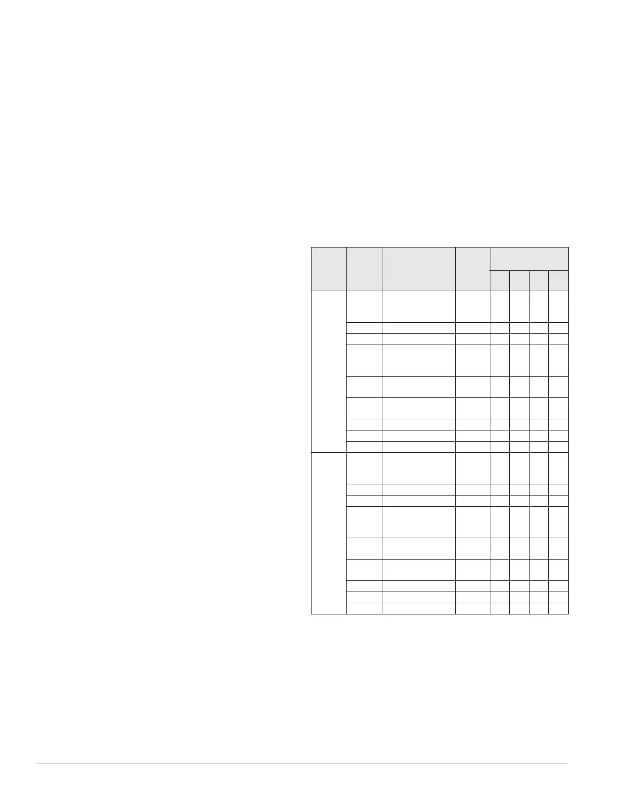
Table 14 summarizes the normal binary output functions and
staging sequencing for the CCB1
and CCB2 for the
2-Comp
ressor/3-Stage cooling configuration. The “X”
characters in Ta
ble 14 indicate that the output is energized for
a particular cooling capacity.
Cooling
circuit
number
Output
number
Description
Action
with
output
on
Cooling capacity
(%)
0 33 66 100
Table 14: Binary outputs for cooling control boards (CCB1
and CCB2): 2-compressors/3-stage
1
(CCB1)
BO1 Compressor #1
(small compressor)
ON/OFf
ON X X
BO2 Not used -
BO3 Not used -
BO4 Circuit # 1 liquid line
solenoid valve
open/close
a
a. Circuit Lead/Lag and Cross Circuit Loading versus Lead Circuit loading do
not apply to this staging configuration.
Open X X
BO5 Condenser fan #11
ON/OFF
ON
b
b. Condenser fan outputs turn on and off based on ambient or evaporative
condensing sump temperature set points adjustable through the unit
keypad.
c. This output is not used on unit equipped with an evaporative conden
ser
and a VFD controlling the first condenser fan on each circuit (Condenser
Fan # 11 and # 21). The VFD controlling these fans is started and stopped
and modulated via RS-485 communications with the main control board.
d. This output is used to open a sump dump valve on units equipped with an
evaporative condenser. Output is energized to open valve.
b
BO6 Condenser fan #12
ON/OFF
ON
bb
BO7 Not used -
BO8
d
Not used -
BO9 Not used -
2
(CCB2)
BO1 Compressor #2 ON/
OFF (large
compressor)
ON X X
BO2 Not used -
BO3 Not used -
BO4 Circuit #2 liquid line
solenoid valve
open/close
a
Open X X
BO5 Condenser fan # 11
ON/OFF
c
ON b b
BO6 Condenser fan # 12
ON/OFF
ON b b
BO7 Not used -
BO8
d
Not used -
BO9 Not used -