Daikin IM 696-4 7
General Description
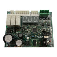
Figure 5: MCB communication interface
U n i t T e r m i n a l
B l o c k T B 2
B A C n e t-
M S T P C O M M .
M O D U L E
5 2 2 ( C L R )
5 2 3 ( B L K )
5 2 2
5 2 3
B A C n e t-
IP
C O M M . M O D U L E
R J 4 5
M O D U L A R
J A C K
R S 2 3 2 P O R T
( D B - 9 M A L E )
S E R IA L C O M M .
L O C A T E D O N
D E A D F R O N T
( D B - 9 M A L E )
B A C n e t
M S T P
L o n W o r k s
B A C n e t
IP
M A IN C O N T R O L B O A R D ( M C B )
S E R V IC E
T O O L
1 0 B A S E - T S T Y L E C O N N E C T IO N
1 2 8
1 2 9
1 2 8
1 2 9
RS-232 Connection Port
A PC loaded with MicroTech II Service Tool software can be
connected directly or via a telephone modem to the RS-232
communications port located on the bottom edge of the MCB.
This connection is shown schematically in Figure 5.
15 VDC Supply Connection
The two 15V terminals located above the analog input
terminals blocks provide 15 VDC power. This power supply is
not used in the rooftop controller application. This power
supply is limited to 30 mA.
CAUTION
Main Control Board LEDs
There are a number of LEDs in various locations on the MCB.
These LEDs consist of three groupings. There are 16 Binary
Input (BI) LEDs located in the upper left corner of the MCB.
These LEDs are lit when the corresponding Binary Input is
turned ON. For information regarding the functions of the
Binary Inputs refer to “Binary Inputs—Main Control Board
(MCB)” on page 23. There are 16 Binary Output (BO) LEDs,
one located next to each Binary Output
on the right side of the
MCB. These LEDs are lit when
the corresponding Binary
Output is turned ON. For information regarding the functions
of the Binary Outputs refer to “Binary Outputs—Main Control
Board (MCB)” on page 24. There are four miscellaneous
LEDs located along the bottom of the
MCB. These LEDs
provide error code in
formation and indication of activity on
the various communication channels. Table 3 lists these LEDs
with their functions.
LED function Location on MCB LED color
MCB error indication*
Red
Off Blinking
*Refer to “Troubleshooting Main Control Board (MCB)” on page 58.
This is an unregulated power supply and should not be used to
feed three-wire potentiometer inputs.
Table 3: Main control board miscellaneous LEDs
RS-485 bus activity indication (LED is ON when activity present on the bus) Left of RS-485 port connector Green
RS-232 port activity indication (LED is ON when activity present at the port) Left of RS-232 port connector Green
BACnet/IP port activity Indication (LED is ON when activity present at the port) Left of BACnet/IP port connector Green
Right of BACnet/IP port connector
Normal Battery low or defective