32 Daikin IM 696-4
Service Information
EERB1
When a unit is equipped with an optional energy recovery
wheel, the system is controlled by an auxiliary energy recovery
control board. The board is designated ERB1. There are nine
binary output relays on the ERB1. These relays are energized
based on commands from the MCB to provide the appropriate
switching action in the energy recovery wheel control
circuitry. The energy recovery wheel control terminals are
wired to these output relays through the binary output
terminals on the left side of the board. Table 21 su
mmarizes
the binary
output connections for the ERB1 board.
Binary
output
Output description
Action with
output ON
ERB1-BO1 Enthalpy wheel
ON/OFF
On
ERB1-BO2 Not used —
ERB1-BO3 Not used —
ERB1-BO4 Close enthalpy wheel bypass dampers Closing
ERB1-BO5 Open enthalpy wheel bypass dampers Opening
ERB1-BO6 Not used —
ERB1-BO7 Decrease enthalpy wheel speed Decreasing
ERB1-BO8 Increase enthalpy wheel speed Increasing
ERB1-BO9 Not used —
Software Identification and Configuration
The MicroTech II control system code is made up of up to four
different software components. All unit applications include a
main control board application code component that resides in
the main control board (MCB). Then, depending on the unit
configuration, there may be one or two cooling auxiliary
control boards, an electric heat auxiliary control board, or an
energy recovery auxiliary control board each loaded with an
application code component.
The application code in the main
control board and any
auxiliary control boards are each ass
igned a ten-digit software
identification number. This includes a seven-digit base number
followed by a three-digit version number.
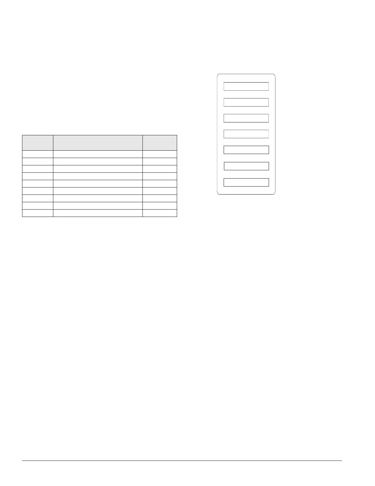
The software identification numbers the unit was loaded with
at the factory appears on the software id
entification label
located near the keypad/display. Figure 16 shows a typical
label. The box labeled “UNIT SOFTWARE NUMBER”
contains the software identification number for the code in the
main controller (MCB). The box labeled “COMPRESSOR
SOFTWARE” contains the software identification number for
the code in the auxiliary cooling control board(s) (CCB1,
CCB2 and GCB1) when applicable. The box labeled “STAGE
ELEC HEAT SOFTWARE” contains the software
identification number for the code in the auxiliary electric heat
control board (EHB1), when applicable. The box labeled
“ENERGY RECOVERY SOFTWARE” contains the software
identification number for the code in the auxiliary energy
recovery control board (ERB1), when applicable.
Note – The “UNIT SOFTWARE NUMBER” loaded into the main
controller (MCB) also appears in the AHUID= parameter
in the Unit Configuration menu on the unit keypad/
display.
Figure 15.
UNIT SOFTWARE NUMBER
SOFTWARE CONFIGURTION CODE
COMPRESSOR SOFTWARE
STAGE ELEC HEAT SOFTWARE
ENERGY RECOVERY SOFTWARE
UNIT G.O.-SEQ NUMBER
2506010146
11780830411002210100211YYY
2506011310
2506012210
2506013210
728121-050
Software identification label
Main Control Board (MCB) Configuration
After the main control board software component is loaded
into the MCB, it must be “configured” for the specific control
application. This consists of setting the value of 20
configuration variables within the MCB. These variables
define things such as the type of cooling, number of
compressors and cooling stages and the type of heat. If all of
these items are not set appropriately for the specific unit, the
unit will not function properly. The correct settings for these
parameters are defined for a given unit by the unit Software
Configuration Code. The Software Configuration Code
consists of a 26-character string of numbers and letters. The
code id located on the unit Software Identification Label on the
back of the door where the unit keypad is mounted. See also
Figure 22 on page 33.
Only the first 22 characters
of this code are used for soft
ware
configuration purposes. The first 22 characters of the Software
Configuration Code currently loaded into a unit controller can
be determined via the unit keypad/display by viewing the six
menu items under the Configuration Code menu. The six menu
items are Pos #1–4=, Pos #5–8=, Pos #9–12=, Pos #13–16=,
Pos #17–20= and Pos #21–22=. The Software Configuration
Code in the unit is determined by combining the values of
these six parameters.
For example, if the six parameters read as Po
s #1–4=1.178,
Pos
#5–8=0.830, Pos #9 12=4.104, Pos #13–16=0.221,
Pos #17–20=0.100 and Pos #21–22=2.0, then the Software
Configuration Code in the unit is 1178083041040221010020.
Note that the decimal points in the values are ignored when
constructing the code. Table 22 on page 33 lists the
configuration code variables includ
ing t
he position within the
code, a description of the parameter, the variable object and
Table 21: Binary outputs for energy recovery wheel control
board (ERB1)