4 Daikin IM 696-4
General Description
Main Control Board (MCB)
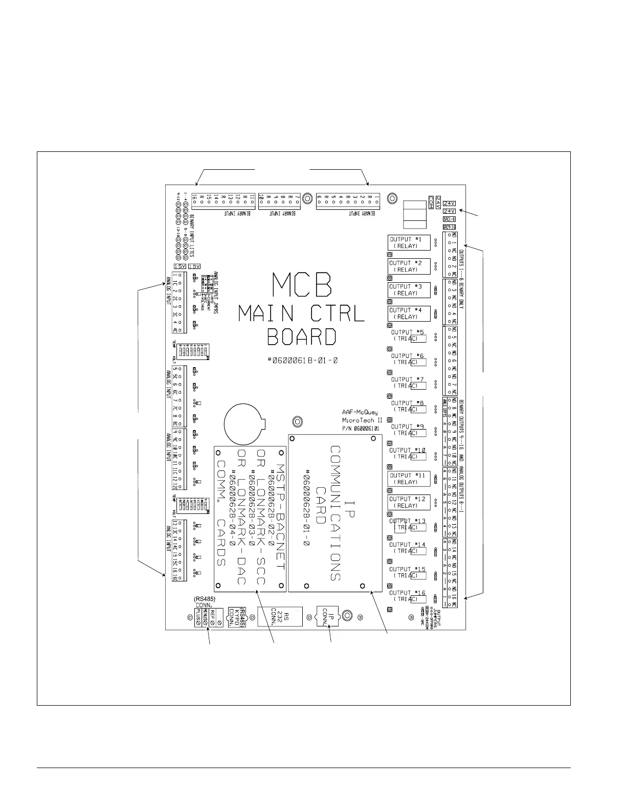
Figure 4 shows the main control board (MCB). It contains a
microprocessor that is programmed with the main application
code to control the unit.
The MCB receives up to 16 analog
and 16 binary inputs directly and up to 6 analog and 12 binary
inputs from each optional auxiliary control board (CCB1,
CCB2, GCB1, EHB1, and ERB1). Auxiliary control boards
communicate this data with the MCB via an RS-485
communication bus interface. The MCB controls its own 16
binary outputs and up to 9 binary outputs on each auxiliary
board based on the inputs.
Figure 4: Main control board
(RS485)
communications
terminal block
RJ-48 jack
Analog inputs
terminal block
Binary outputs
terminal block
Power suppl
terminal
Binary inputs
terminal blocks
BACnet/IP
communication
module
BACnet MS/TP
or L
ON W ORKS
communication
module