60 Daikin IM 696-4
Test Procedures
MCB LED Startup Error Codes
The 16 green Binary Input LEDs in the upper left corner and
miscellaneous LEDs on the bottom (3 green and 1 red) of the
MCB (Refer to Figure 28 on page 59) can be used to diagnose
problems with the MCB.
During the MCB Error Code Display period, MCB failures are
indicated by the red MCB Error LED o
n the bottom right side
turning ON or BLINKING along with one other LED turning
ON according to Table 24 on page 60. If multiple error
conditions exist, each error code appears in suc
cession, lasting
approximately 3 seconds each, and
then turn OFF. Non-
catastrophic errors are indicated during the MCB Error Code
Display period with the red MCB Error LED remaining on
continuously.
All non-catastrophic errors are logged i
n RAM to be retrieved
by the MCB operating system. Catastrophic errors are
indicated during the MCB Error Code Display period with the
red MCB Error LED flashing at a rate of approximately 5.9
Hz. When the MCB Error Code Display period is complete,
the startup sequence continues.
The following diagnostic tests are run during the startup
sequence:
• Battery Te
st
• Flash CRC (Cyclic Redundancy Check) Test
• SRAM (Static RAM) Test
• Communication Port Tests
• IP Register Test
The following sections
provide
a brief description of each of
these startup tests and recommended steps to correct the
probl
em.
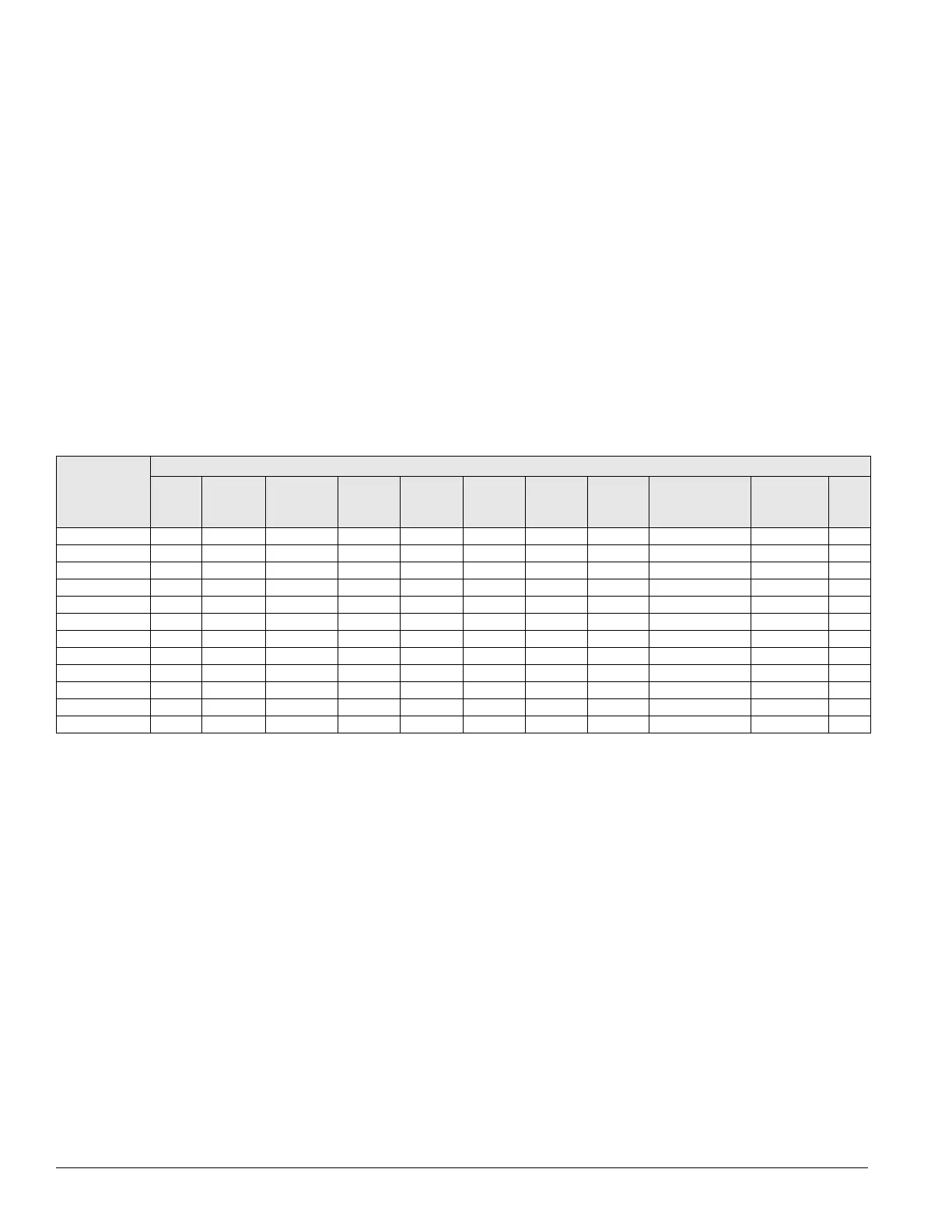
LED
Startup errors
Battery
Flash
CRC
startup
Flash CRC
main/boot
Flash
CRC
config.
RAM
low
byte
RAM
high
byte
RS 485
bus
port
RS 232
port
BACnet MS/TP
or L
ONMARK
port (optional)
I/O
expansion
port
IP
port
Table 24: Main control board LED startup error codes
RS-485 bus port ON
RS-232 port ON
IP port ON
MCB error ON Blinking Blinking Blinking Blinking Blinking ON ON ON ON ON
BI-1 ON
BI-2 ON
BI-3 ON
BI-4 ON
BI-5 ON
BI-6 ON
BI-7 ON
BI-8 ON

 Loading...


