Daikin IM 696-4 31
Service Information
GCB1 (RDS & RAH)
For RDS and RAH model air handling units interfaced with
generic condensing units, the cooling stages are controlled by
an auxiliary control board loaded with special generic
condensing unit control software. This board is designated
GCB1. There are nine binary output relays on the GCB1.
These relays are energized based on commands received from
the MCB to provide the appropriate switching action in the
condensing unit control circuitry. The condensing unit control
circuit terminals are wired to these output relays through the
binary output terminals on the left side of the board.
These cooling outputs are ener
gized and de-ener
gized
sequentially to maintain the cooling load. The outputs are
sequentially turned on whenever the cooling capacity is
increased. The outputs are sequentially turned off whenever
the cooling capacity is decreased.
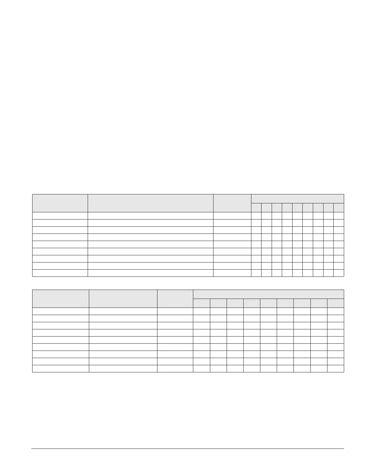
This sequence of one output per stage is shown in Table 19 on
page 31. With this arrangement, protec
tion of the compressors
and control of condenser fans
are not provided by the
MicroTech II controller but rather by the condensing unit
co
ntrol system.
EHB1
When a unit is equipped with a multiple stage electric heater
the heat is controlled by an auxiliary electric heat control
board. The board is designated EHB1. There are nine binary
output relays on the EHB1 board. These relays are energized
based on commands from the MCB to provide the appropriate
switching action in the electric heat control circuitry. The
electric heat control terminals are wired to these output relays
through the binary output terminals on the left side of the
board.
These heating outputs are energized and de-energized
sequen
tially to ma
intain the heating load. These outputs are
sequentially turned on whenever the heating capacity is
increased. These outputs are sequentially turned off whenever
the heating capacity is decreased. The sequence of one output
per stage is shown in Table 20.
Output # Output description
Action with
output ON
Cooling stage
0 1 2 3 4 5 6 7 8
GCB1-BO1 Cooling stage #1 ON/OFF On X X X X X X X X
GCB1-BO2 Cooling stage #2 ON/OFF On X X X X X X X
GCB1-BO3 Cooling stage #3 ON/OFF On X X X X X X
GCB1-BO4 Cooling stage #4 ON/OFF On X X X X X
GCB1-BO5 Cooling stage #5 ON/OFF On X X X X
GCB1-BO6 Cooling stage #6 ON/OFF On X X X
GCB1-BO7 Cooling stage #7 ON/OFF On X X
GCB1-BO8 Cooling stage #8 ON/OFF On X
GCB1-BO9 Not used —
Output # Output description
Action with
output on
Heating stage
0 1 2 3 4 5 6 7 8
EHB1-BO1 Heating stage #1
ON/OFF
ON X X X X X X X X
EHB1-BO2 Heating stage #2
ON/OFF
ON X X X X X X X
EHB1-BO3 Heating stage #3
ON/OFF
ON X X X X X X
EHB1-BO4 Heating stage #4
ON/OFF
ON X X X X X
EHB1-BO5 Heating stage #5
ON/OFF
ON X X X X
EHB1-BO6 Heating stage #6
ON/OFF
ON X X X
EHB1-BO7 Heating stage #7
ON/OFF
ON X X
EHB1-BO8 Heating stage #8
ON/OFF
ON X
EHB1-BO9 Not used —
Table 19: Binary outputs for cooling control board (CCB21): RDS or RAH with up to 8 DX cooling stages
Table 20: Binary outputs for electric heat control board (EHB1): up to 8 heat stages