30 Daikin IM 696-4
Service Information
3-Compressors/4-Stage. In this configuration there are
two equally sized small compressors in Cooling Circuit #1 and
one large compressor in Cooling Circuit #2. The cooling
outputs are always controlled in the same way.
There is no
circuit lead/lag operation with this configuration.
Starting with 0% cooling capacity, when
a capacity increase is
requ
ired, the small compressor on circuit #1 with the fewest
run hours is turned on (25%). When a further capacity increase
is required, the remaining compressor on circuit #1 is turned
on (50%). When a further capacity increase is required, the
large compressor on circuit #2 is turned on and the small
compressor on circuit #1 with the most run hours is turned off
(75%). When a further capacity increase is required, the small
compressor on circuit #1 that is not operating is turned on
(100%).
Starting with 100% capacity, when a capacity
decrease is
requ
ired, the small compressor on circuit #1 with the most run
hours is turned off (75%). When a further capacity decrease is
required, the large compressor on circuit #2 is turned off and
the small compressor on circuit #1 that is not operating is
turned on (50%). When a further capacity decrease is required,
the small compressor on circuit #1 with the most run hours is
turned off (25%). When a further capacity decrease is required,
the operating small compressor on circuit #1 is turned off (0%)
Note – If one of the small compressors on circuit #1 is disabled,
the unit stages between 25% (using the enabled small
compressor on circuit #1) and 75% (small compressor on
circuit #1 and large compressor on circuit #2) skipping
the 50% capacity step. If both of the small compressors
on circuit #1 are disabled, the large compressor on circuit
#2 (50% capacity) cycles on and off to maintain the load.
If the large compressor on circuit #2 is disabled, the two
small compressors on circuit #1 cycles on and off (based
on run hours) to maintain the load.
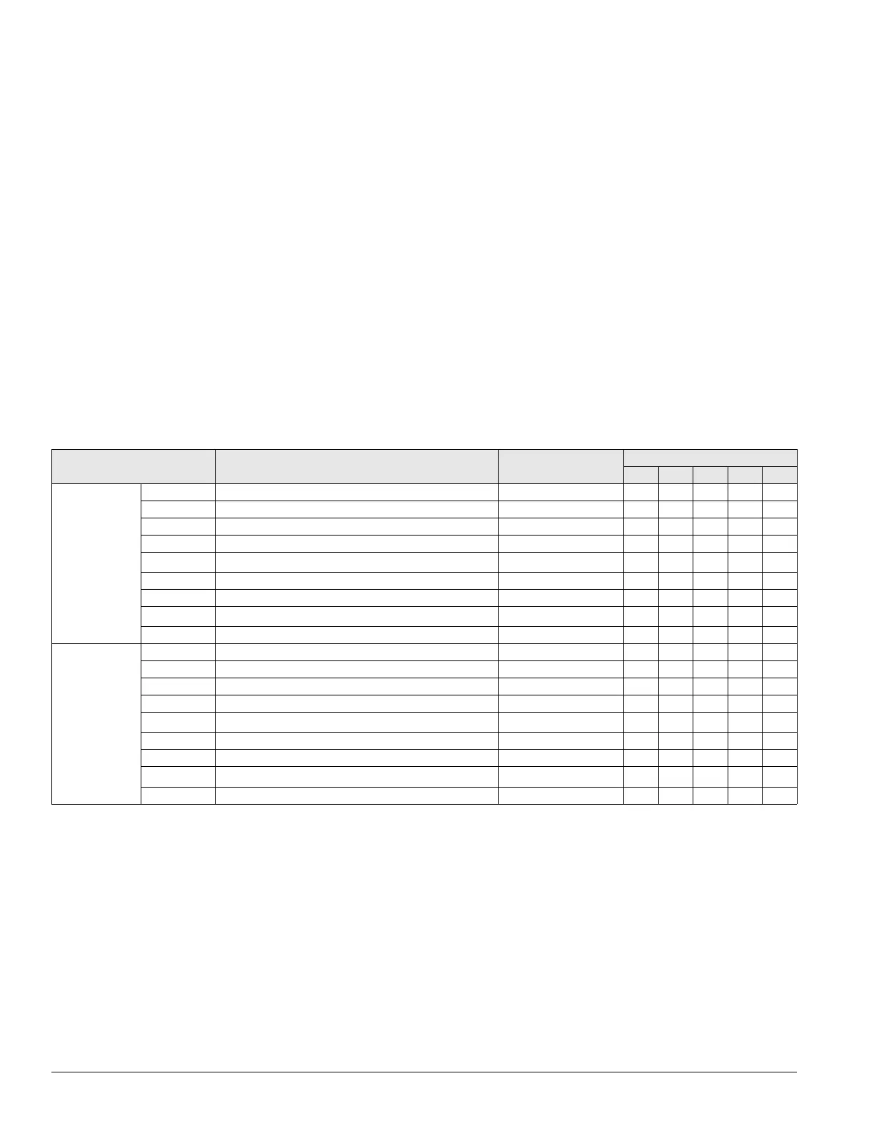
Table 20 on page 31 summarizes the normal binary output
functions and staging sequencing for CCB1 and CCB2 for the
3 Com
pressors/4 Stage cooling configuration. The Xs in the
table indicate that the output is energized for a particular
cooling capacity.
Cooling circuit #
output
Description Action with output ON
Cooling capacity (%)
0 25 50 75 100
1 (CCB1)
BO1 Compressor # 1 ON/OFF (small compressor) On X X X X
BO2 Compressor # 3 ON/OFF (small compressor) On b X b X
BO3 Not used —
BO4 Circuit # 1 liquid line solenoid
valve open/close Open X X X X
BO5
Conde
nser fan # 11 ON/OFF
d
On c c c c
BO6 Condenser fan # 12 ON/OFF On c c c c
BO7 Condenser fan # 13 ON/OFF On c c c c
BO8
Not used
e
—
BO9 Not used —
2 (CCB2)
BO1 Compressor # 2 ON/OFF On X X
BO2 Not used On
BO3 Not used —
BO4 Circuit # 2 liquid line solenoid valve open/close Open X X
BO5
Conde
nser fan # 21 ON/OFF
d
On c c
BO6 Condenser fan # 22 ON/OFF On c c
BO7 Condenser fan # 23 ON/OFF On c c
BO8
Not used
e
—
BO9 Not used —
a. Circuit Lead/Lag does not apply to this staging configuration.
b. If Compressor #3 has fewer run hours it operates instead of Compressor #1 at this cooling capacity.
c. Condenser fan outputs turn on and off based on ambient or evaporative condenser sump temperature set points adjustable through the unit keypad.
d. This output is not used on unit equipped with an evaporative condenser and a VFD controlling the first condenser fan on each circuit (Condenser Fan # 11 and
# 21).
The VFD controlling these fans is started and stopped and modulated via RS-485 communications with the main control board.
e. This output is used to open a sump dump valve on units equipped with an evaporative condenser. Output is energized to open valve.
Table 18: Binary outputs for cooling control boards (CCB1 & CCB2): 3-compressors/4-stage (circuit #1 lead)
a