Daikin IM 696-4 29
Service Information
4-Compressors/8-Stage. In this configuration there are four
equally sized compressors and two cooling circuits.
Compressor #1 and Compressor #3 are in Cooling Circuit #1
and Compressor #2 and Compressor #4 are in Cooling Circuit
#2. Compressor #1 and Compress
or #2 each have one
unloader. Compressor #3 and Compressor #4 have no
unloading. Each cooling circuit is controlled in the same way.
One circuit is designated the “Lead” and the other the “Lag”
circuit. For detailed information regarding circuit lead/lag
operation, refer to the applicable operation manual (refer to
Table 1 on
page 1).
There are two
methods for controlling
the two circuits when
both are enabled: Cross Circuit Loading and Lead Circuit
Loading. For details regarding selecting Cross Circuit Loading
versus Lead Circuit Loading, refer to the “Compressor
Staging” section of the applicable operation manual (refer to
Table 1 on page 1).
Cross Circuit Loading. With this method, the two circuits are
alternately loaded and unloaded as evenly as possible.
The normal staging sequence is as follows:
When a capacity increase is required an
d both circuits are
operating at the same capacity, the “Lead” circuit is staged up
if not already at its maximum. When a capacity increase is
required and both circuits are not operating at the same
capacity, the “Lag” circuit is staged up if not already at its
maximum capacity. When a capacity decrease is required and
both circuits are operating at the same capacity, the “Lag”
circuit is staged down. When a capacity decrease is required
and both circuits are not operating at the same capacity, the
“Lead” circuit is staged down.
Lead Circuit Loading. With this method, one circuit is loaded
completely before the first compressor in the other circuit is
turned on, and one circuit is unloaded completely before the
other circuit is unloaded.
The normal staging sequence is as follows:
When a capacity increase is required and the “Lead” circuit is
not at
maximum, the “Lead” circuit is staged up. When a
capacity increase is required and the “Lead” circuit is already
at its maximum stage, the “Lag” circuit is staged up. When a
capacity decrease is required and the “Lag” circuit is not at
zero capacity, the “Lag” circuit is staged down. When a
capacity decrease is required and the “Lag” circuit is at zero
capacity, the “Lead” circuit is staged down.
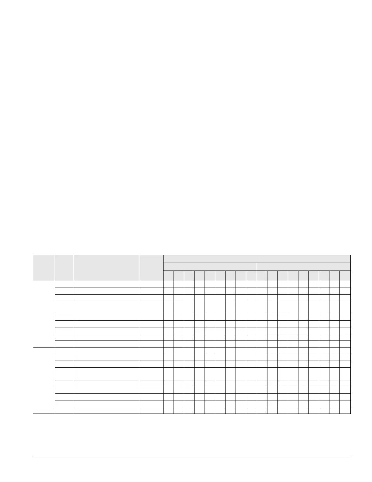
Table 17 on page 29 sum
marizes the normal binary output
functions and staging sequencing for CCB1 and CCB2 for
the
4 Compressors/8 Stage Lead Circuit Loading cooling
configuration. The Xs in the table indicate that the output is
energized for a particular circuit cooling capacity.
With either the Cross Circuit Loading or Lead Circuit Loading
method
s, a disabled circuit remains at zero capacity. If the
other circuit is enabled, it acts as the “Lead” and the circuit
capacity is controlled using the Lead Circuit Loading method
as shown in Table 17.
Cooling
circuit #
Outpu
t #
Description
Action
with
output
ON
Cooling capacity (%)
Cross circuit loading Lead circuit loading
0 12 25 37 50 62 75 87 100 0 12 25 37 50 62 75 87 100
a. If Circuit #2 is the “lead” circuit, interchange the data in the table between CCB1 and CCB2 for the correct output staging data.
b. Condenser fan outputs turn on and off based on ambient or evaporative condenser sump temperature set points adjustable through the unit keypad.
c. This output is not used on unit equipped with an evaporative condenser and a VFD controlling the first condenser fan on each circuit (Condenser Fan # 11 and
# 21).
The VFD controlling these fans is started and stopped and modulated via RS-485 communications with the main control board.
Table 17: Binary outputs for cooling control boards (CCB1 and CCB2): 4-compressors/8-stage
1 (CCB1)BO1Compressor #1 ON/OFF ON XXXXXXXX XXXXXXXX
BO2Compressor # 3 ON/OFF ON XXXX XXXXXX
BO3 Unloader #1, Compressor #1 Unloaded X X X X X X X
BO4 Circuit # 1 liquid line solenoid
valve open/close
Open XXXXXXXX XXXXXXXX
BO5 Condenser fan #11 ON/OFF
c
ON bbbbbbbb bbbbbbbb
BO6Condenser fan #12 ON/OFF ON bbbbbbbb bbbbbbbb
BO7Condenser fan #13 ON/OFF ON bbbbbbbb bbbbbbbb
BO8Condenser fan #14 ON/OFF ON bbbbbbbb bbbbbbbb
BO9 Not used —
2 (CCB2) BO1 Compressor #2 ON/OFF ON X X X X X X X X X X X
BO2 Compressor #4ON/OFF ON X X X X X
BO3 Unloader #1, compressor #2 Unloaded X X X X X X
BO4 Circuit # 1 liquid line solenoid
valve open/close
Open XXXXXXX XXXX
BO5 Condenser fan #21 ON/OFF
c
ON bbbbbbb bbbb
BO6Condenser fan #22 ON/OFF ON bbbbbbb bbbb
BO7Condenser fan #23 ON/OFF ON bbbbbbb bbbb
BO8Condenser fan #24 ON/OFF ON bbbbbbb bbbb
BO9 Not used —