Cooling
circuit
number
Output
number
Description
Action
with
output on
Cooling capacity (%)
Cross circuit loading Lead circuit loading
0 25 50 75 100 0 25 50 75 100
28 Daikin IM 696-4
Service Information
a. If Circuit #2 is the “lead” circuit, interchange the data in the table between CCB1 and CCB2 for the correct output staging data.
b. If Compressor #3 has fewer run hours it operates instead of Compressor #1 at this cooling capacity.
c. If Compressor #4 has fewer run hours it operates instead of Compressor #2 at this cooling capacity.
d. Condenser fan outputs turn on and off based on ambient or evaporative condenser sump temperature set points adjustable through the unit keypad.
e. This output is applicable on 060C size units only.
f. This output is not used on unit equipped with an evaporative condenser and a VFD controlling the first condenser fan on each circuit (Condenser Fan # 11 and
# 21). The VFD controlling these fans is started and stopped and modulated via RS-485 communications with the main control board.
g. This output is used to open a sump dump valve on units equipped with an evaporative condenser. Output is energized to open valve.
a. If Circuit #2 is the “lead” circuit, interchange the data in the table between CCB1 and CCB2 for the correct output staging data.
b. If Compressor #5 has fewer run hours it operates instead of Compressor #1 or Compressor # 3 at this cooling capacity.
c. If Compressor #6 has fewer run hours it operates instead of Compressor #2 or Compressor #4 at this cooling capacity.
d. Condenser fan outputs turn on and off based on ambient or evaporative condenser sump temperature set points adjustable through the unit keypad.
e. This output is applicable on 075C size units only, or on units equipped with an evaporative condenser in which case the output is used to open a sump dump
valve when energized.
f. This output is not used on unit equipped with an evaporative condenser and a VFD controlling the first condenser fan on each circuit (Condenser Fan # 11 and
# 21). The VFD controlling these fans is started and stopped and modulated via RS-485 communications with the main control board.
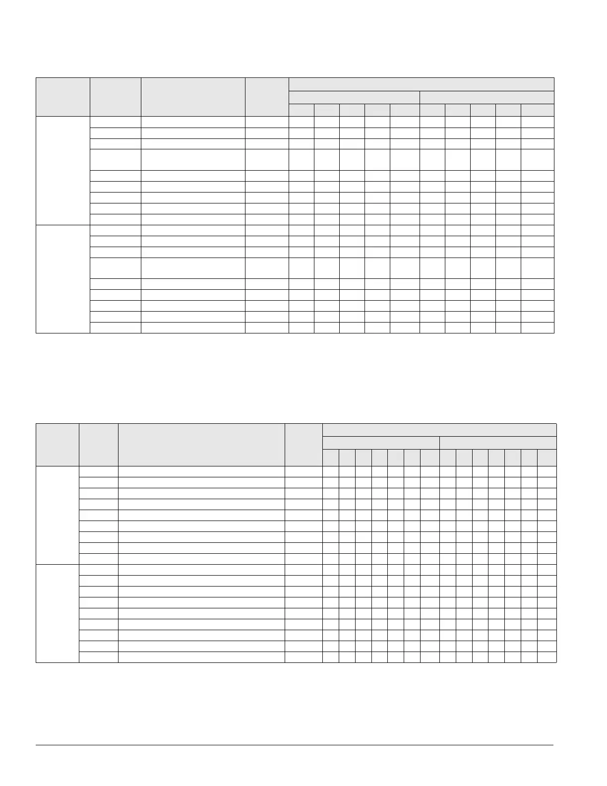
Table 15: Binary outputs for cooling control boards (CCB1 and CCB2): 4-compressors/4-stage (circuit #1 lead)
a
1 (CCB1) BO1 Compressor #1 ON/OFF ON X X X X X X X X
BO2 Compressor #3 ON/OFF ON b b X X b X X X
BO3 Not used —
BO4 Circuit #1 liquid line solenoid
valve open/close
Open XXX X XXX X
BO5 Condenser fan #11 ON/OFF
f
ON ddd d ddd d
BO6 Condenser fan #12 ON/OFF ON d d d d d d d d
BO7 Condenser fan #13 ON/OFF
e
ON ddd d ddd d
BO8
g
Not used
g
—
BO9 Not used —
2 (CCB2) BO1 Compressor #2 ON/OFF ON X X X X X
BO2 Compressor #4 ON/OFF ON c c X c X
BO3 Not used —
BO4 Circuit #1 liquid line solenoid
valve open/close
Open X X X X X
BO5 Condenser fan #21 ON/OFF
f
ON d d d d d
BO6 Condenser fan #22 ON/OFF ON d d d d d
BO7 Condenser fan #23 ON/OFF
e
ON d d d d d
BO8
g
Not used —
BO9 Not used —
Table 16: Binary outputs for cooling control boards (CCB1 and CCB2): 6-compressors/6-stage (circuit #1 lead)
a
Cooling
circuit #
Output # Description
Action
with
output
ON
Cooling capacity (%)
Cross circuit loading Lead circuit loading
0 16 33 50 66 83 100 0 16 33 50 66 83 100
1 (CCB1)
BO1 Compressor #1 ON/OFF ON XXXXX X XXXXX X
BO2 Compressor #3 ON/OFF ON bbXXX X bXXXX X
BO3 Not used —
BO4 Circuit #1 liquid line solenoid valve open/close Open XXXXX X XXXXX X
BO5 Condenser fan #11 ON/OFF
f
ON ddddd d ddddd d
BO6 Condenser fan #12 ON/OFF ON ddddd d ddddd d
BO7 Condenser fan #13 ON/OFF ON ddddd d ddddd d
BO8 Condenser fan # 14 ON/OFF
e
ON ddddd d ddddd d
BO9 Compressor #5 ON/OFF ON b b b b X X b b X X X X
2 (CCB2)
BO1 Compressor #2 ON/OFF ON X X X X X X X X
BO2 Compressor #4 ON/OFF ON c c X X X c X X
BO3 Not used —
BO4 Circuit #2 liquid line solenoid valve open/close Open X X X X X X X X
BO5 Condenser fan #21 ON/OFF
f
ON dddd d dd d
BO6 Condenser fan #22 ON/OFFf ON dddd d dd d
BO7 Condenser fan #23 ON/OFF ON dddd d dd d
BO8 Condenser fan #24 ON/OFF
e
ON dddd d dd d
BO9 Compressor #6 ON/OFF ON c c c c X c c X