18 Daikin IM 696-4
Field Wiring
Humidity Sensors
When the MicroTech II controller is conf
igured for constant
volume zone temperature control (SCC), a dehumidification
sequence is available and can be activated through the keypad.
In order to use this function, an optional factory-supplied,
field-mounted humidity sensor is required.
Either a wall mount or duct mount sensor is available. The
sensor m
ust be wired to termi
nals 126
, 12
7 and 131 on the unit
field terminal block (TB2). Terminal 126 is wired to OUT (0–5
VDC), terminal 127 to GND and terminal 131 to PWR on the
humidity sensor. These terminals are factory wired to the MCB
analog input MCB-AI12. The input must be 0–5 VDC as the
relative humidity varies from 0–100%. Refer to the unit wiring
diagrams or Figure 18 on page 42 for wiring termination
details.
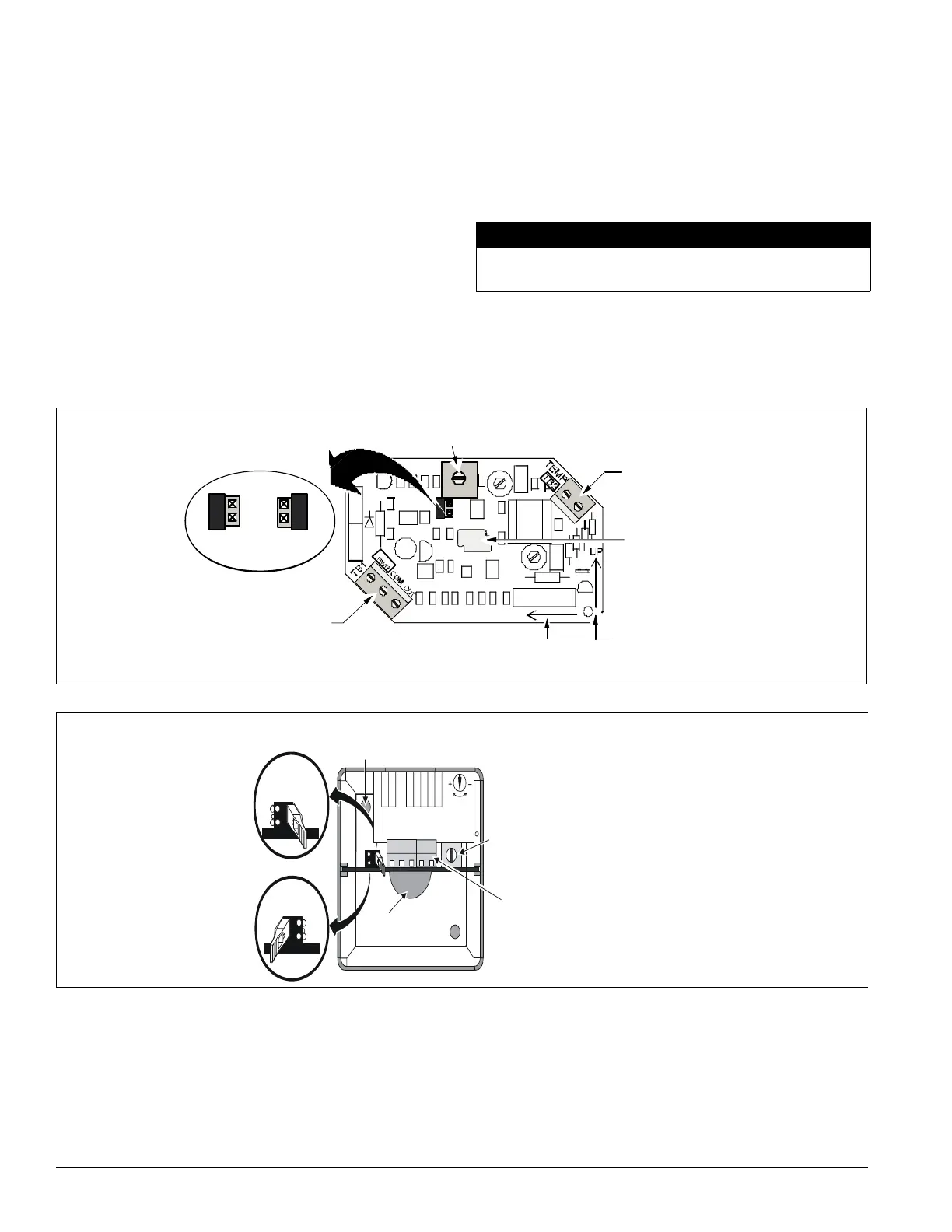
Note – The output select jumper (J1) on the sensor must be in
the 0–5 VDC position. The TEMP terminals on the
sensor are not used (see Figure 10 or Figure 11 on
page 18).
Field wire the humidity sensor wiring to terminals 126 and 127
to the unit using a twisted pair, shielded cable (Belden 8761 or
equivalent). Cable with 22 AWG conductors is sufficient.
CAUTION
Note – Set the analog input jumper associated with MCB-AI12
to the no jumper (NJ-VDC) position. Set the analog input
dip switch associated with this input to the ON (V)
position.
Figure 10: Humidity sensors (wall mount)
Output adjustment
jumper
0 to 5V
0 to 10V
Terminal block TB1
Output adjustment
potentiometer
Output Adjust
Up
Terminal bl
Wiring ope
Mounting
direction
arrows
Figure 11: Humidity sensor (duct mounted)
0–5 V
Output jumper
Wiring block
(screw terminals
are accessed
through the cutout
in the housing.)
Of fset adjustment
potentiometer
Screw hole
Screw hole
Probe
0–10 V
Output jumper
(factory set)
OUTPUT
SELECTION
INPUT18-30V AC,12-30VDC
OUTPUT0-10,OR0-5VDC
TERMINAL
DESIGNA TION
OFFSET
ADJUST
DA TE
0-5V
0-10V
PWR
OUT
TEMP
TEM P
COM
Do not install this cable in the same conduit as power wiring.
Such installation can cause unit malfunction.