Daikin IM 696-4 23
Service Information
Analog Inputs—Auxiliary Control Boards (CCB1,
CCB2, GCB1, EHB1 & ERB1)
The optional auxiliary control boards (CCB1, CCB2, GCB1,
EHB1 and ERB1) h
ave up to six analog inputs available.
However, in this product application, these are used only on
the ERB1. Analog inputs ERB1-A1 and ERB1-A2 are
configured for temperature sensor inputs. The remainder are
spare inputs.
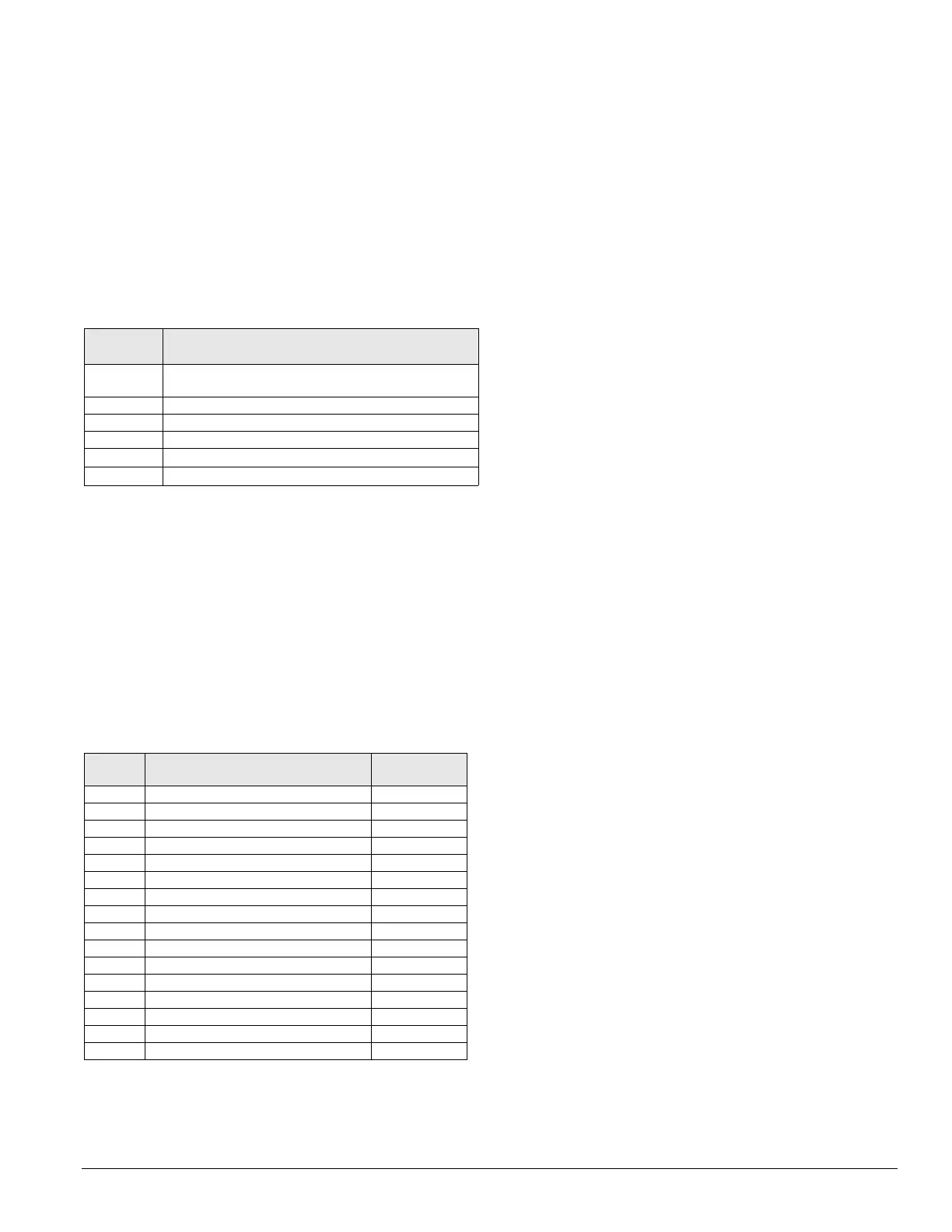
Refer to Table 9 for a description of each analog input on the
ERB1 board.
Analog
input
Input description
ERB1-AI5 Not used
ERB1-AI6 Not used
Binary Inputs—Main Control Board (MCB)
The 16 binary inputs to the MCB are in the form of 0 VAC
(off
) or 24 VAC (on) applied to the binary input terminals.
Transformer T2 is the source of this the 24 VAC for these
inputs.
Each binary input has an LED associated with it that lights
when 24
VAC is present at the corresponding inpu
t terminal.
These binary input LEDs are grouped together and are located
in the upper left had corner of the board. Table 10 summarizes
the binary input functions and LED indications for the binary
inp
uts to th
e MCB.
Binary Inputs—Auxiliary Control Boards
(CCB1,
CCB2, GCB1, EHB1 & ERB1)
The optional auxiliary control boards include 12 binary inputs.
Inputs BI1 throug
h BI6 are designed for a set of dry contacts
between the COM terminal and the individual binary input
terminals on J9. BI7 through BI12 are designed for 24 VAC
inputs (input is ON when 24 VAC is present at the
corresponding input terminal on J10 and OFF when 0 VA C i s
no
t present)
. The following sections described how these
inputs are defined for each of the auxiliary control boards.
Note – The set of two jumpers in the upper right corner of the
board (below the RS-485 Communications module) must
both be placed on the right most pins. Placing the jumper
on the left most pins interlocks binary inputs BO1 with
BI1 and BO2 with BI2 respectively. This interlock is not
used on this product application
CCB1 & CCB2 (7RPS, RFS/RCS, RDT, RPR & RFR)
When a unit is equipped with a factory condensing unit, each
of the two cooling circuits is controlled with an auxiliary
control board. Circuit #1 is controlled by the CCB1 and circuit
#2 is controlled by the CCB2. Table 10 and Table 11 on
page 24 summarize the binary inputs for the C
CB1 and
CCB2
respectively.
GCB1 (RDS & RAH)
When a rooftop air handling unit is interfaced with a field
supplied condensing unit, the cooling stages in the condensing
unit are controlled by a generic condenser auxiliary control
board. This board is designated GCB1. In this case only
GCB1-BI12 is defined in the GCB1 control software. It is a
“cool enable” input. Cooling is enabled when 24 VAC is
present and disabled when 24 VAC is not present at this input.
This input is supplied to the GCB1 through a “cooling enable”
output from the MCB.
EHB1
When a unit is equipped with multistage electric heat, the
heating stages are controlled by an electric heat auxiliary
control board. This board is designated EHB1. In this case
only EHB1-BI12 is defined for the EHB1. It is a “heat enable”
input. Heating is enabled when 24 VAC is present and disabled
when 24 VAC is not present at this input. This input is supplied
to the EHB1 through a “heating enable” output from the MCB.
ERB1
When a unit is equipped with an optional energy recovery
wheel system, the system is controlled by an energy recovery
auxiliary control board. This board is designated ERB1. None
of the binary inputs are used on the ERB1.
Table 9: Analog inputs for energy recovery wheel control
board (ERB1)
ERB1-AI1 Leaving energy recovery wheel temperature (exhaust),
optional
ERB1-AI2 Leaving energy recovery wheel temperature (discharge)
ERB1-AI3 Not used
ERB1-AI4 Not used
Table 10: Binary inputs for main control board (MCB)
Binary
input
Input description
Lit LED
indication
MCB-BI1 External Time clock or tenant override Occupied
MCB-BI2 Manual system disable Disabled
MCB-BI3 Remote cool enable Enabled
MCB-BI4 Remote heat enable Enabled
MCB-BI5 Gas furnace flame failure alarm Alarm
MCB-BI6 Airflow status Airflow detected
MCB-BI7 Freeze alarm for steam or hot water coils Normal
MCB-BI8 Smoke alarm: supply air, return air or both Normal
MCB-BI9 First filter switch Normal
MCB-BI10 Final filter switch (optional) Normal
MCB-BI11 Outdoor enthalpy status
a
a. Not used on 100% outdoor air units.
Low OA enthalpy
MCB-BI12 Not used —
MCB-BI13 External exhaust fan status (optional)
b
b. Applicable only on VAV units configured for “fan tracking” return fan
control.
On
MCB-BI14 Duct hi limit
c
c. Applicable on VAV units only.
Normal
MCB-BI15 Not used —
MCB-BI16 Not used —