Binary Input Input Description 24 VAC Present Indication
CCB1-BI1 Compressor #5 Contactor Auxiliary Switch Status M5 Contactor Energized
CCB1BI2 Not Used -
CCB1-BI3 Not Used -
CCB1-BI4 Not Used -
CCB1-BI5 Not Used -
CCB1-BI6 Circuit #1 Low Pressure Switch Status (LP1) Switch Closed
CCB1-BI7 Circuit #1 High Pressure Switch Status (HP1 or HP3) Normal
CCB1-BI8 Circuit #1 Frost Protection Switch Status (FP1) Normal
CCB1-BI9 Compressor #1 Contactor Auxiliary Switch Status M1 Contactor Energized
CCB1-BI10 Compressor #3 Contactor Auxiliary Switch Status M3 Contactor Energized
CCB1-BI11 Circuit #1 Pumpdown Switch Status Switch Closed
CCB1-BI12 Circuit #1 Cool Enable Input Enabled
Binary Input Input Description 24 VAC Present Indication
CCB2-BI1 Compressor #6 Contactor Auxiliary Switch Status M6 Contactor Energized
CCB2-BI2 Not Used -
CCB2-BI3 Not Used -
CCB2-BI4 Not Used -
CCB2-BI5 Not Used -
CCB2-BI6 Circuit #2 Low Pressure Switch Status (LP2) Switch Closed
CCB2-BI7 Circuit #2 High Pressure Switch Status (HP2 or HP4) Normal
CCB2-BI8 Circuit #2 Frost Protection Switch Status (FP2) Normal
CCB2-BI9 Compressor #2 Contactor Auxiliary Switch Status M2 Contactor Energized
CCB2-BI10 Compressor #4 Contactor Auxiliary Switch Status M4 Contactor Energized
CCB2-BI11 Circuit #2 Pumpdown Switch Status Switch Closed
CCB2-BI12 Circuit #2 Cool Enable Input Enabled
24 Daikin IM 696-4
Service Information
Controller Outputs
Binary Outputs—Main Control Board (MCB)
The main control board has 16 binary outputs that provide unit
control
in response to input conditions. Binary outputs
energize on-board electromechanical relays (BO1 through
BO4, BO11 and BO12) or triacs (BO5 through BO10 and
BO13 through BO16). Unit control devices are wired to the
relays and triacs through six output terminal blocks located on
the right side of the MCB.
There are three terminals associated with
each binary output.
The terminals associated with BO1 are labeled NO, 1, and
NC,
the terminals associated with BO2 are labeled NO, 2, and NC,
and so forth. Each binary output has an LED associated with it
that lights when the corresponding output relay or the triac is
turned on.
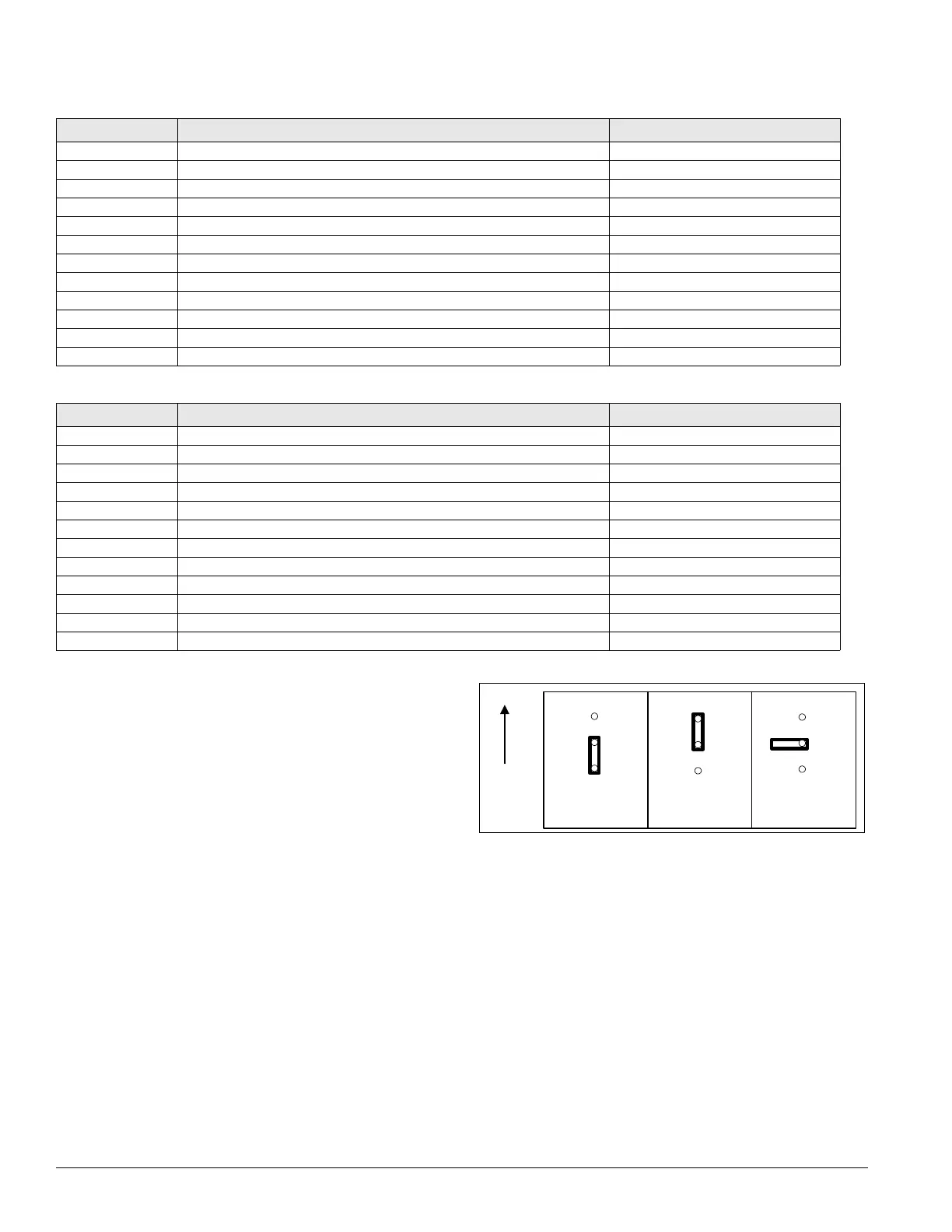
Each binary output has an output jumper associated with it.
The
th
ree jumper positions are: 1-SRC V (jumper on the
bottom two pins), 2-BRD24V (jumper on the top two pins) and
3-OFFBRD (no jumper). Refer to Figure 14.
Figure 14. Binary output jumper (MCB)
2 - BRD24V
(Not Used)
1 - SRC V. 3-OFFBRD
Top
of
MCB
When the jumper is in position 1-SRC V, 24 VAC from the
SRC 1-8 terminal (BO1 through BO8) or the SRC 9-16
terminal (BO9 through BO16) is applied to the numbered
terminal of the associated outputs. In the case of BO1 through
BO4, BO11 and BO12, this signal is then delivered to either
the NC terminal when the corresponding output is off (output
relay de-energized) or the NO terminal when the
corresponding output is on (output relay energized). In the case
of BO5 through BO10 and BO13 through BO16, this signal is
then delivered to the NO terminal when the corresponding
output is on (triac energized). Transformer T3 furnishes 24
VAC to the SRC 1-8 terminal and the SRC 9-16 terminal. This
jumper configuration is used when a specific binary output is
used to energize a 24 VAC pilot relay in the unit. Refer to
Table 13 on page 25 for the correct jumper position for all the
standard binary outputs.
Table 11: Binary inputs for circuit #1 auxiliary cooling control board (CCB1)
Table 12: Binary inputs for circuit #2 auxiliary cooling control board (CCB2)