56 Daikin IM 696-4
Typical Wiring Diagrams
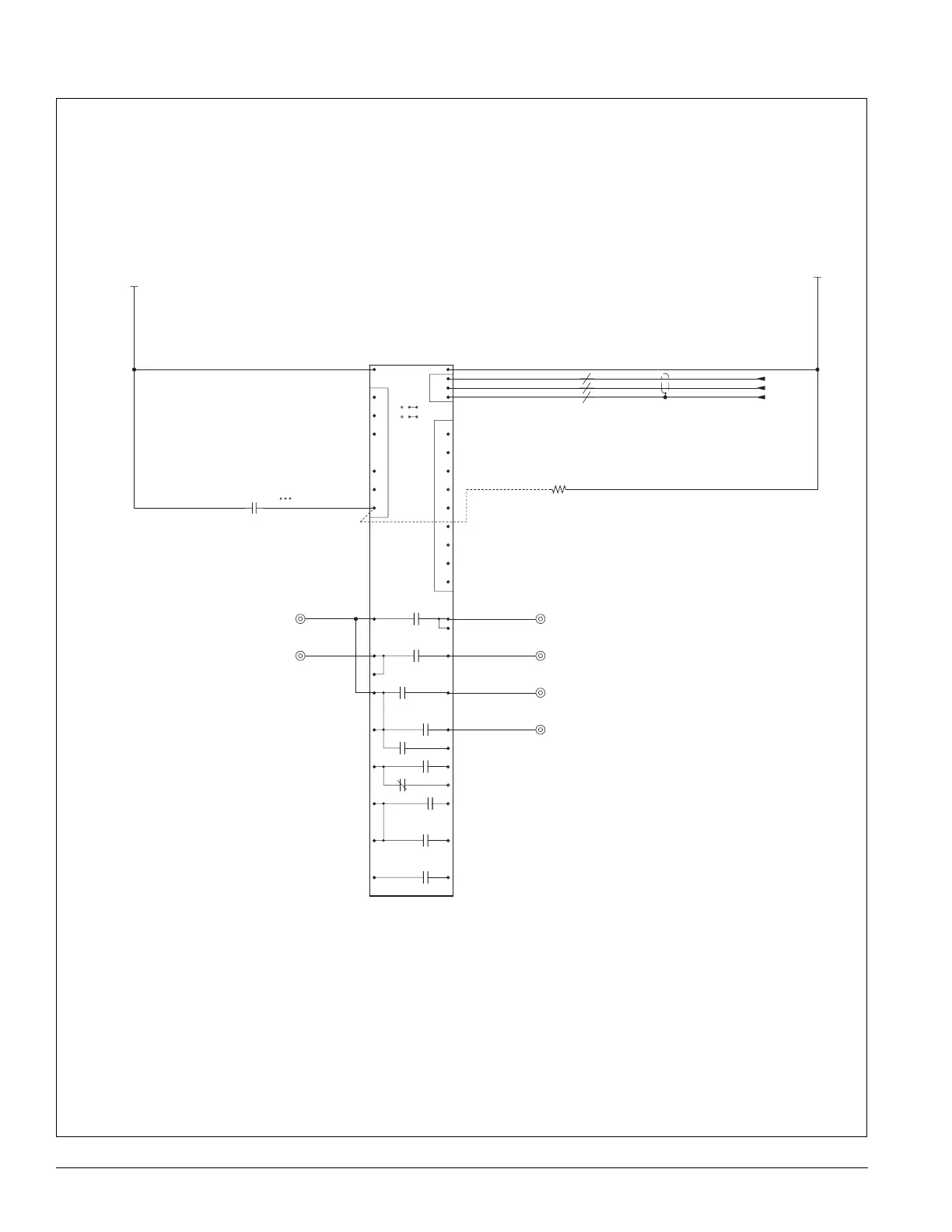
Figure 25:
(OPEN OUTPUT)
(OPEN OUTPUT)
(OPEN OUTPUT)
(OPEN OUTPUT)
(OPEN OUTPUT)
(OPEN OUTPUT)
TO COOLING STAGE #4
TO COOLING STAGE #3
TO COOLING STAGE #2
TO COOLING STAGE #1
277V, 5A RESISTIVE
120V, 1/10HP, 3FLA, 18LRA, 100VA PILOT DUTY
240V, 1/4HP, 2.9FLA, 17.4LRA, 250VA PILOT DUTY
277V, 1/3HP, 2.98FLA, 17.88LRA, 300VA PILOT DUTY
BINARY OUTPUT ELEC. RATINGS
JUMPERS
ENABLE
DISABLE
BO1
ENABLE
DISABLE
BO2
(JUMPER LOCATED
JUST UNDER
COMM CARD)
1.3K OHM, 2W
801
802
803
804
805
806
807
808
809
810
811
812
813
814
815
816
817
818
819
820
821
822
823
824
825
826
827
828
829
830
831
832
833
834
835
836
837
838
839
840
841
842
843
844
845
846
847
848
849
850
851
852
853
854
855
856
207
BO7
NOCOM
NCCOM
BO6
BO8
NOCOM
BO9
NOCOM
BO1
NOCOM
BO4
NOCOM
BO5
NOCOM
BO6
NOCOM
BO3
NOCOM
BO2
NOCOM
J10
J8
INPUTS
BI=BINARY
AI=ANALOG
GENERIC.
CONDENSER
BOARD
N2
BUS
24V SRC
jprs
?
211
221
212
213
210
220
WHT
BLK
DRN
2019
1817
16 15
14
12 13
11
910
87
6
54
3
2
1
5VDC
COM
AI3
AI6
COM
AI2
5VDC
COM
AI1
REF
N2-
N2+
24C
BI12
BI11
BI8
BI10
BI9
BI7
24V
8
7NO7
TB4
TB4
TB4
TB4
REF/2.11
N2+/2.10
N2-/2.10
24VT3
24VNT3
TB4
TB4
GCB1
RESISTOR
MCB B07
834A
832A
830B
828B
830A
828A
823A
210D
209C
210C
Generic condenser control (4 stage)