www.DaikinApplied.com 19 IM 1267-7 • PRECISELINE AIR HANDLER
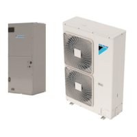
Figure 35: Size 006 - 020 Hydronic Coil Drill Areas – Top
and Right Side
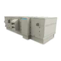
Figure 36: Field Pipe Connections, Unit Sizes 030, 040, 050
Figure 37: AVD Hydronic Coils
All AVD Units (vertical units Size 06-20) have coil connections
located in the unit. The connections are FPT as default, and
M-SWT if selected. There are pilot holes on both sides and the
the location of the pilot holes. The diameter of the hole should
be no more than 1/2" larger than the pipe, and the gap around
the pipe should be sealed after installation.
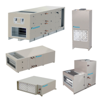
Figure 38: AVD-020 Field-Cut Hole Locations
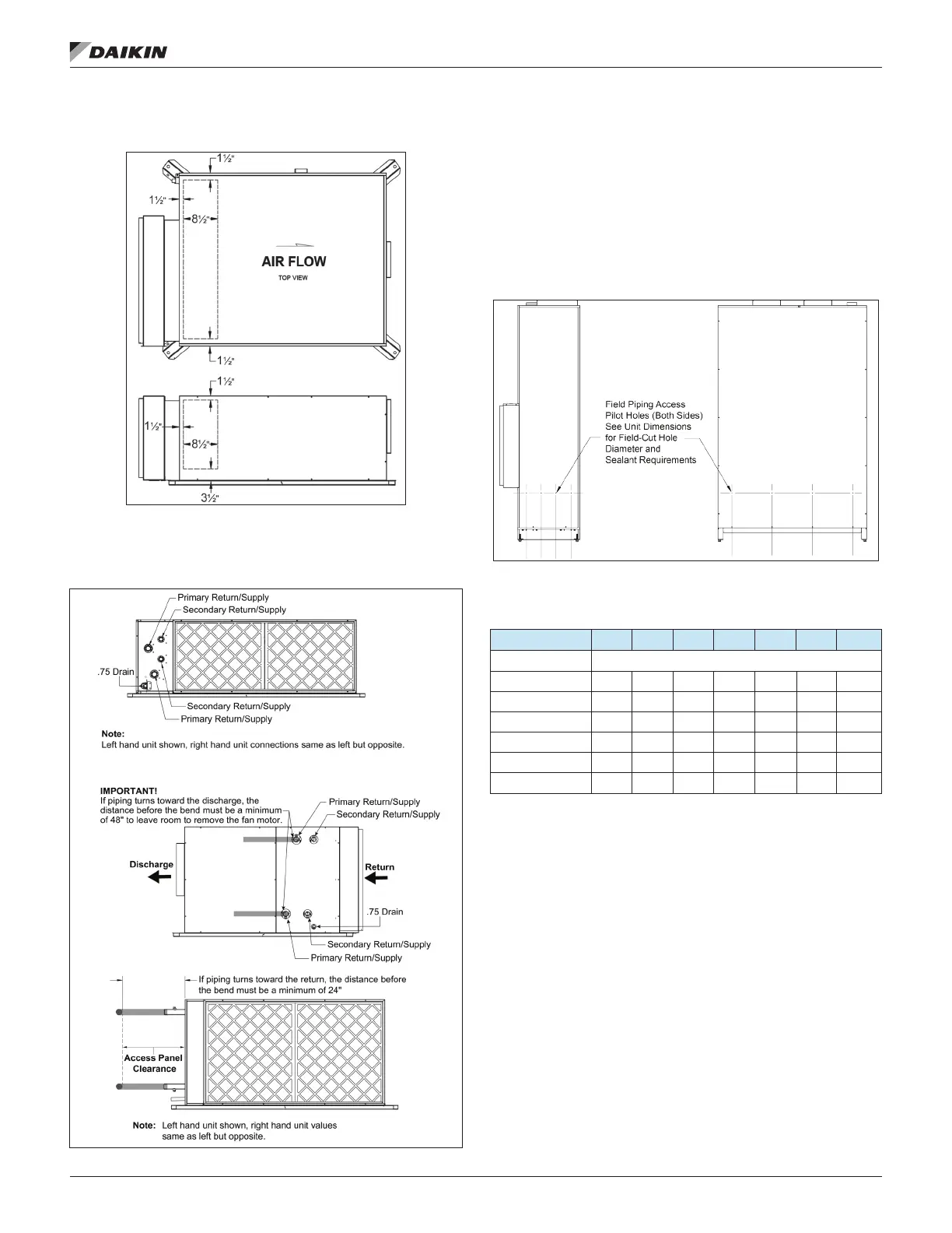
Table 5: Hydronic Coil Connection Size and Type with No
Piping Option
6 8 10 12 16 18 20
Connection Type M-SWT (OD)
2-Row Cooling 0.625 0.625 0.625 0.625 0.875 0.875 0.875
4-Row Cooling 0.625 0.625 0.875 0.875 0.875 1.125 1.125
6-Row Cooling 0.625 0.875 0.875 0.875 1.125 1.125 1.125
8-Row Cooling
1-Row Heating 0.625 0.625 0.625 0.625 0.625 0.625 0.625
2-Row Heating 0.625 0.625 0.625 0.625 0.875 0.875 0.875
 Loading...