IM 1267-7 • PRECISELINE AIR HANDLER 6 www.DaikinApplied.com
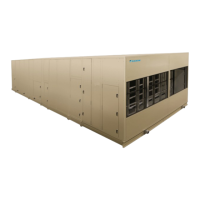
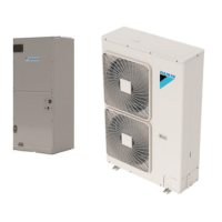
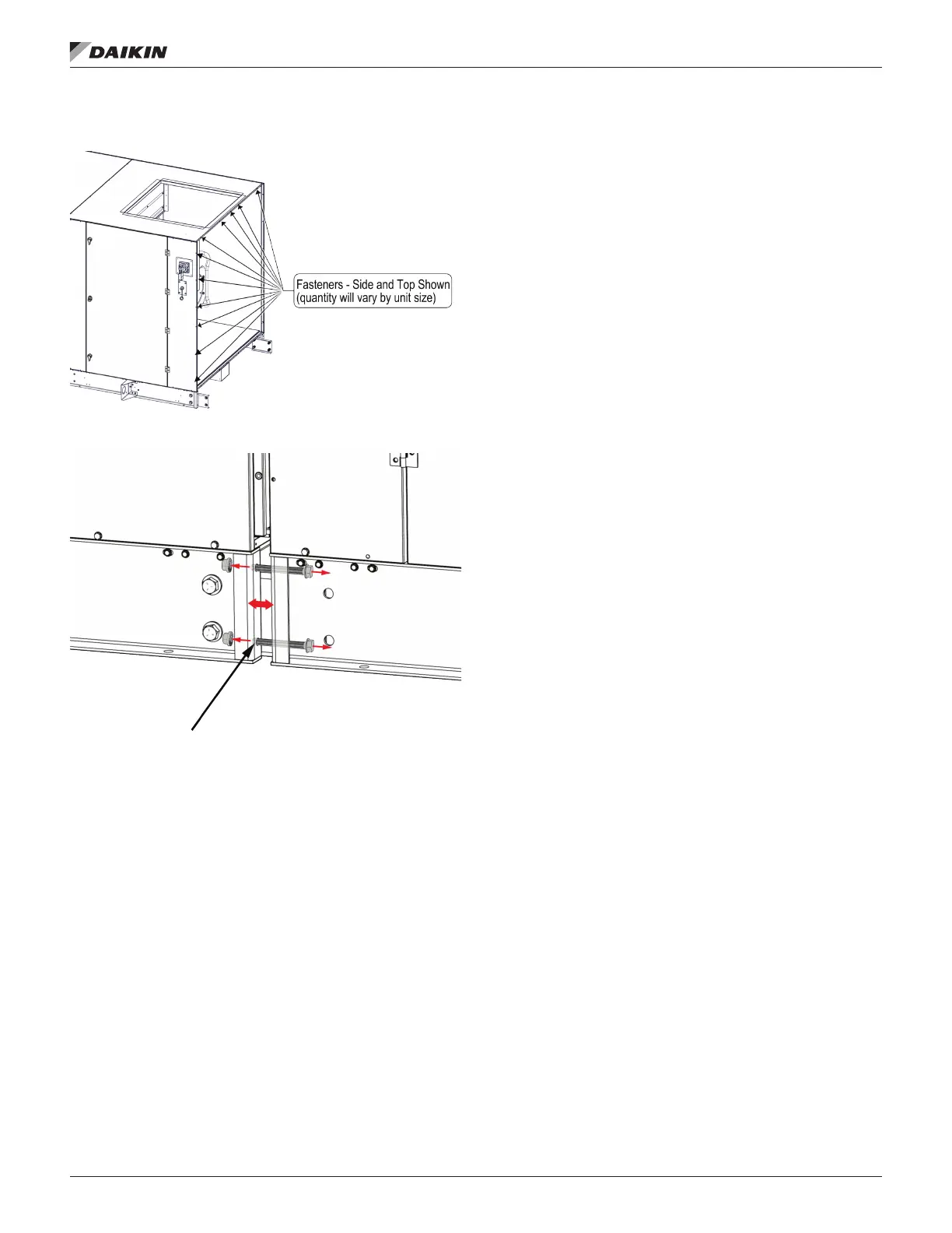
Figure 4: Size 100 Unit - Disassembling Optional Mixing
Box
Leave adequate space around the unit for piping, coils, and
drains. Always have access to at least one side of the unit
for regular service and maintenance. Refer to images on the
following pages for servicing space requirements. Routine
and coil removal, if necessary. For routine maintenance,
remove service panels on either side of the unit. See Figure
22 panel removal on page 15
service panel removal and to meet the service clearance
requirement of the section it accesses. Service panels are not
interchangeable with service panels on the opposite side of the
unit. Leave at least 42" of clearance in front of electrical power
devices (starters, VFDs, disconnect switches, and combination
devices) mounted behind service panels.
 Loading...