IM 1267-7 • PRECISELINE AIR HANDLER 18 www.DaikinApplied.com
Follow applicable piping design, sizing, and installation
information presented in ASHRAE Handbooks in the design
and installation of piping. Observe all local codes and industry
standards. Do not apply undue stress at the connection to the
coil headers. Support pipe work independently of the coils.
Hydronic coil guidelines are listed below.
1. Horizontal units have hydronic coil stubs extend
connections made outside the cabinet. Stub locations
are the same for preheat and reheat coils. All stubs are
labeled on the panel.
2. Supply and return connections are copper FPT on unit
sizes 006 through 020 and copper sweat on sizes 030
through 100. See Horizontal Hydronic Coil Size and
Connection Type on page 67.
3. When making threaded connections, do not apply
undue stress to the stub. Use a backup wrench to avoid
damaging the braze joint between the stub and the valve
package or coil. When making sweat connections the
cabinet and valves must be protected from heat damage.
Use wet cloths or a heat shield to prevent heat from
soldering from burning the paint and insulation around
the stub.
4. Entering air below 40°F is not recommended.
Extended periods of temperatures below freezing can
cause some components to function improperly.
5. If fresh air and return air are to be heated by a hot water
coil, take care in the design of the system to provide
thorough mixing before air enters the coil.
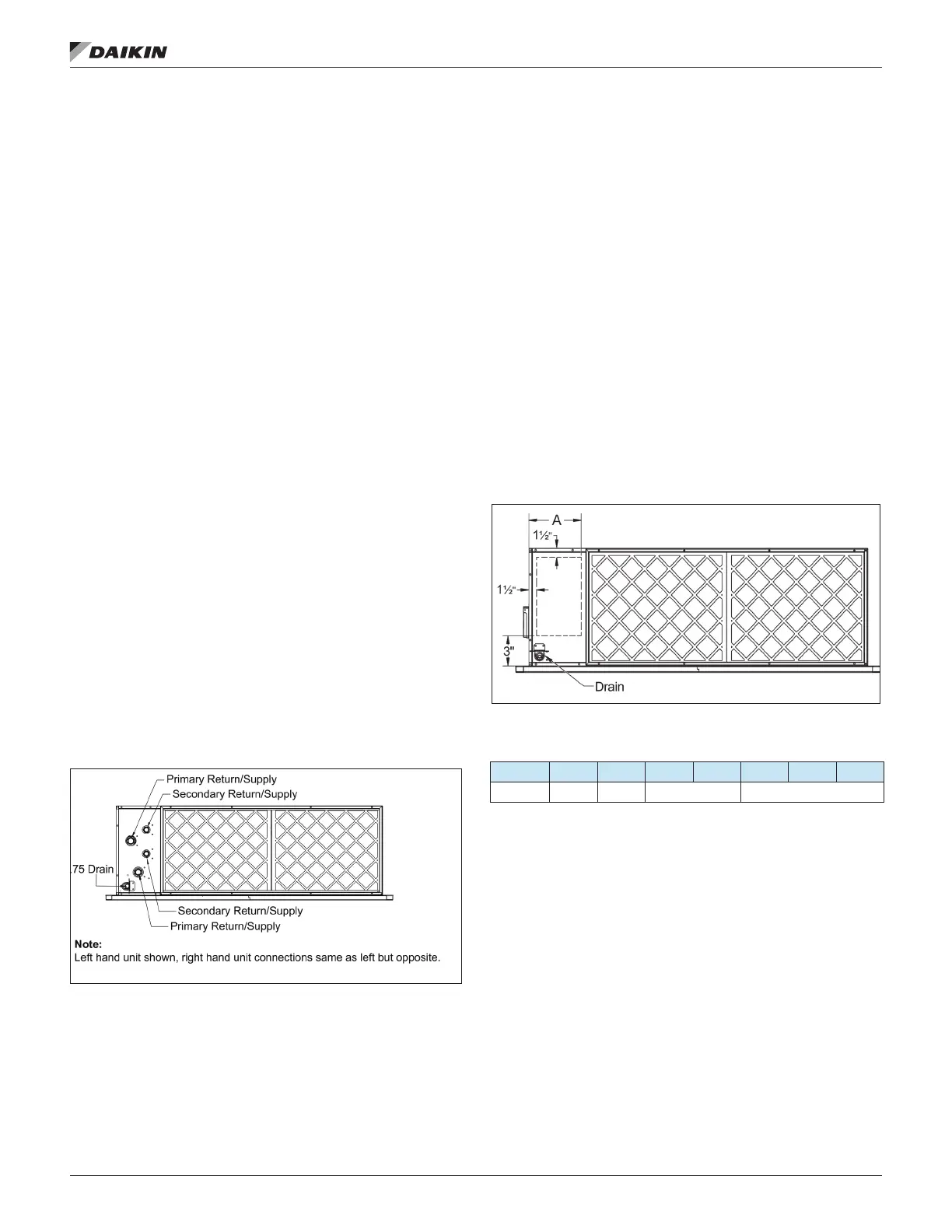
Figure 33: Horizontal Coil Connections, Unit Sizes 006
Thru 020
Hydronic coil guidelines for units selected with the "No Valve
Package - Threaded Connections" option are listed below.
Refer to Table 5 on page 19 for connection size and type.
1. The supply and return coil stubs terminate inside the
made inside the cabinet. All stubs are factory labeled.
2. Internal hydronic coil connections are M-SWT.
be completely within the drill area on one of the factory
designated panels. (See Figure 34 below and Figure 35
on page 19) The diameter of the hole should be no
more than 1/2" larger than the pipe and gap around the
pipe should be sealed after installation.
4. When making the sweat connection the cabinet, coil and
drain pan must be protected from heat damage. Use wet
cloths or a heat shield to prevent the heat from soldering
from burning the paint and insulation around the stub.
Figure 34: Size 006 - 020 Hydronic Coil Drill Area - Front
Table 4: Size 006-020 Hydronic Coil Drill Area Dimensions
006 008 010 012 016 018 020
A 7.13 7.80 7.62 7.53
 Loading...