Electrical Installation
8
3 Electrical Installation
CAUTION:Onlyqualiedindividualsshouldperformroutingandterminationtothe
display� Electrical contractors are responsible for ensuring that all electrical work meets
or exceeds local and national codes� Daktronics engineering staff must approve all
changes or the warranty will be void�
Installation Overview
Reference Drawings:
Block Diagram: AS5000 BB- VB and WR #1 ...................................................... DWG-124686
Block Diagram: AS5000 BB- VB and WR #3 ...................................................... DWG-124688
Block Diagram, A/S 3000 or 5000 Hockey ........................................................ DWG-124689
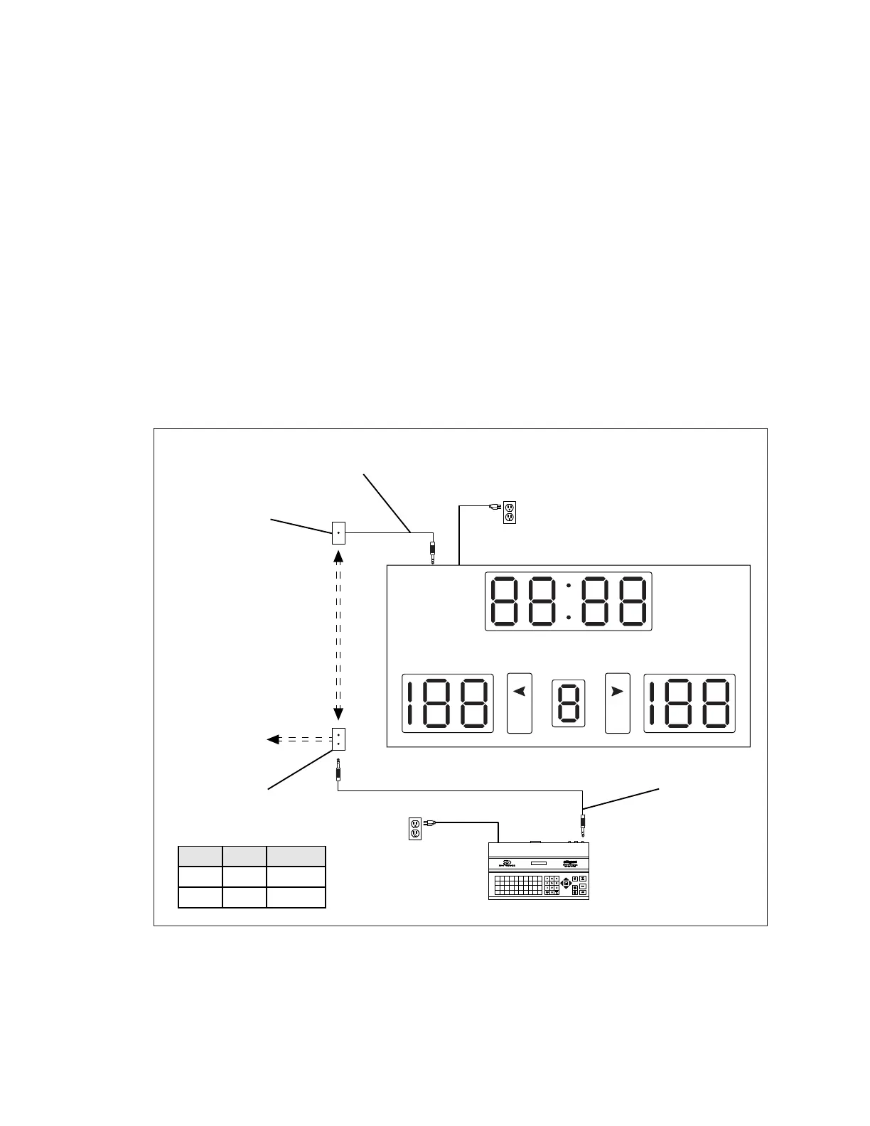
Figure 9 illustrates a wired setup between a scoreboard and controller. Daktronics part
numbers are shown in parentheses. DWG-124686, DWG-124688, and DWG-124689 in
Appendix B also show power and signal layouts.
Control signal cable and some junction boxes are not provided as part of this system and
can be purchased locally or from Daktronics.
daktronics
PERIOD
GUESTHOME
BB
Signal Cable:
10' (W-1340)
20' (W-1236)
30' (W-1238)
50' (W-1237)
J1, J2,
or J3
J31 -
SIGNAL IN
All Sport Controller
J-Box:
Dual 1/4" Phone
(0A-1196-0013)
Pin Color Function
tip red signal +
ring black signal -
J-Box:
(Not provided by
Daktronics)
To Main Power
Signal Cable:
1 Pair, 22 AWG
(W-1077)
in Conduit
Signal Cable:
1/4" Male Phone to Pigtail, 10'
(0L-40683)
[To Aux
Scoreboard]
Figure 9: Wired Installation