Mechanical Installation
4
2 Mechanical Installation
Mechanical installation consists of lifting and permanently mounting the display(s).
The product specication sheets listed in Appendix A include installation specication
drawings that show the recommended number and spacing of wall anchors for specic
scoreboard models. Be sure that the installation complies with local building codes.
Note: Daktronics assumes no liability for installations derived from the information
provided in this manual or installations designed and installed by others.
Lifting
Most displays and display sections ship equipped with at least one 1/2" shoulder-type
eyebolt located along the top of the cabinet for the purpose of lifting. Smaller game/
shot clocks do not require eyebolts and are not equipped with them.
Note: Daktronics assumes no liability for damages resulting from incorrect setup or lifting
methods. Eyebolts are intended for lifting only. Do not attempt to permanently
support the display by the eyebolts.
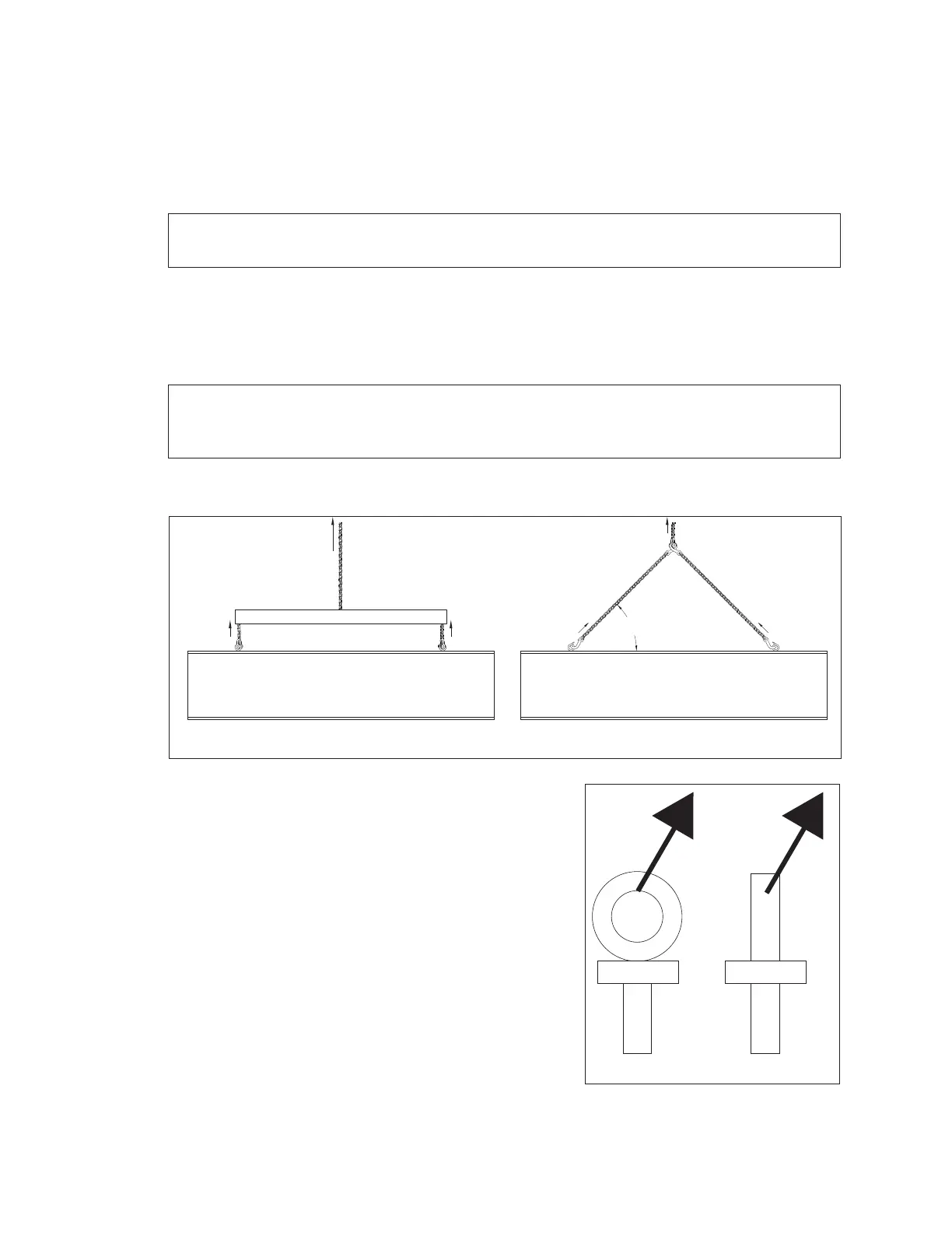
For displays with two eyebolts, use a spreader bar, or lifting bar, to lift the display�
Spreader bars ensure force on the eyebolts remains straight up, minimizing lifting stress.
Figure 3 illustrates the preferred lifting method on the
left and an acceptable alternative lifting method on
the right. When lifting the cabinet:
• Use a spreader bar if possible.
• Use every lifting point provided.
Avoid using other lifting methods. Cables and chains
attached to the eyebolts and directly to a center
lifting point, as shown in the “Acceptable” example
in Figure 3, can create a dangerous lateral force on
the eyebolts and may cause them to fail. The smaller
the angle between the cable and the top of the
cabinet, the lighter the cabinet must be to safely lift
it. If this method must be used, ensure a minimum
angle between the chain and cabinet of at least 45°.
Preferred
Lifting Bar
45° Minimum
Acceptable
Figure 3: Lifting Methods
Figure 4: Eyebolt Plane Load