Electrical Installation
10
Lightning Protection
The use of a disconnect near the display to completely cut all current-carrying lines
signicantly protects the circuits against lightning damage. Local and national electrical
codes also may require it. In order for this system to provide protection, the power must
be disconnected when the display is not in use.
The control console should also be disconnected from power and from the signal
junction box when the system is not in use. The same surges that may damage the
display components can also damage the console’s circuitry.
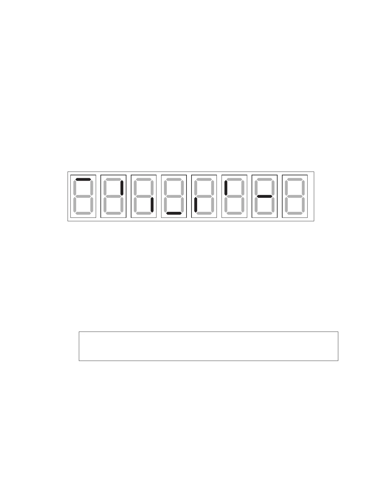
Power-On Self-Test (POST)
The display performs a self-test each time that power is turned on and the control
console is powered off or not connected. If the control console is connected and
powered on, the self-test does not run, and data from the control console appears on
the display after a few seconds. Each self-test pattern will vary depending on the model,
the number of drivers, and types of digits. Figure 11 shows an example of the LED bar test
pattern that each digit performs.
Figure 11: Digit Segment POST
Wired Signal Connection
Reference Drawings:
Signal Connection; Installation ........................................................................... DWG-28124
Schematic; Dual 1/4" Phone J-box w/ Shunt Jack ......................................... DWG-125316
Wired signal installation requires routing control cable from the control console to a signal
junction box (J-box) near the display. Refer to Figure 9 for typical signal layout. Refer also
to DWG-28124 and DWG-125316 in Appendix B for signal wire connection. At a minimum,
use a paired, 22 AWG shielded cable (Daktronics part # W-1077).
1� Connect the cable to a dual 1/4" J-box at the control console end.
Note: Using a dual J-box for separate Main and Auxiliary scoreboards lets operators
control several displays with one controller, and they can also switch jacks to
control individual displays using multiple controllers.
2� Route the cable in conduit from the J-box on the control console end to a J-box near
the display.
3� Install the 1/4" phone plug (part # 0L-40683) to the display end of the cable. Be sure
to connect the cable shielding only in the J-box on this end. DO NOT connect cable
shielding at the J-box near the control console.
4� Insert the plug into the J31 – SIGNAL IN jack located on the top of the display.
5� Connect a signal cable from the J-box on the control console end to the J1, J2, or J3
jack on the back of the All Sport 5000/5500 console (or J1/J2 on the All Sport 1600).
6� If using a Main Clock Start/Stop Switch (0A-1166-0003), connect it to the J4 jack on
the All Sport 5000/5500 console.