Mechanical Installation
5
Do NOT attempt to lift the cabinet if the angle is less than 45°. Exceeding load angles or
weight limits could cause the bolts in the cabinet to buckle, resulting in serious damage
to the equipment or injury to personnel. Also, loads should be applied directly in the
plane of the eyebolt as shown in Figure 4.
Small displays that are not equipped with eyebolts instead use two lifting straps that
encircle the cabinet. The use of a spreader bar with the straps is recommended.
Wall Mounting
Due to the variety of wall materials used in sports
facilities, Daktronics cannot anticipate a user’s
individual installation needs or provide mounting
hardware suitable for every installation. Choose a
method of installation that will safely support the
weight of the display.
Single-Section Displays
1� Use the eyebolt(s) at the top of the display
cabinet to lift it into position for mounting.
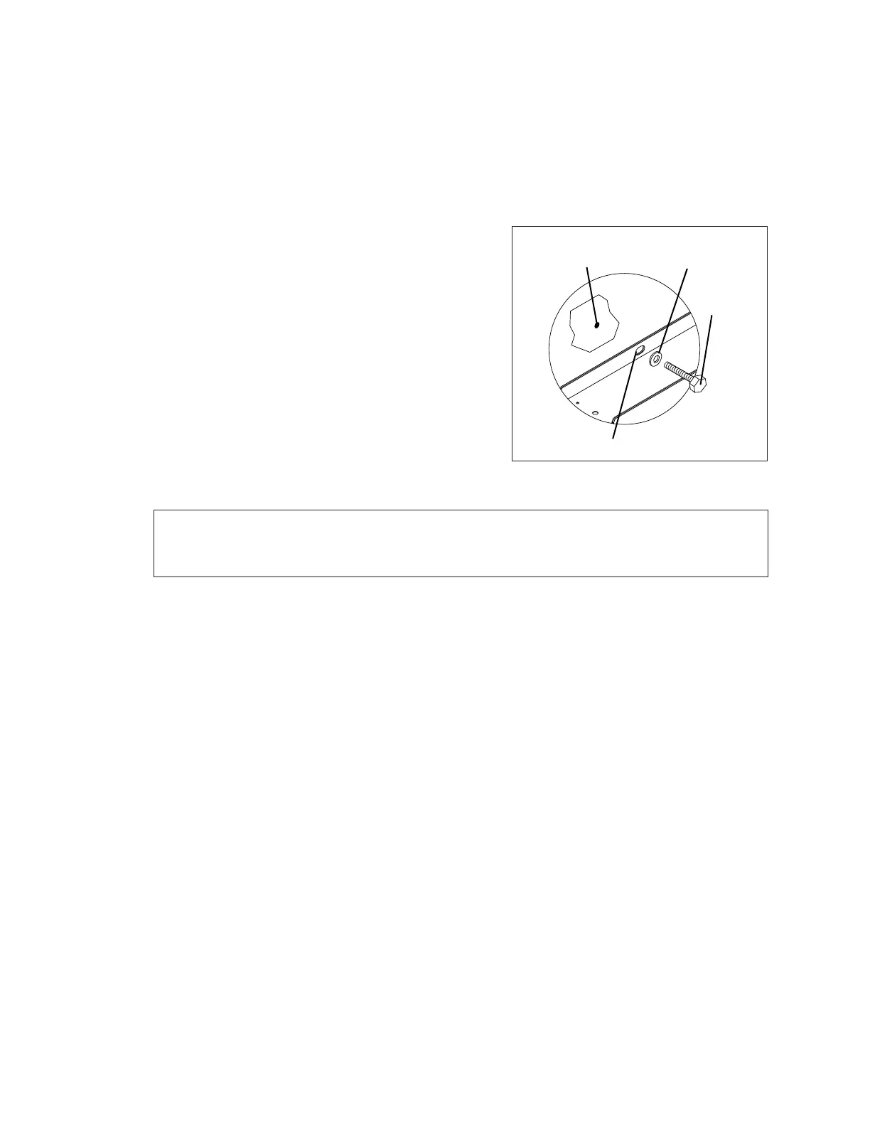
2� Secure the display to the wall by attaching
mounting hardware through all holes on the
top and bottom rear anges of the cabinet to
a pre-drilled hole in the wall (Figure 5).
Note: For basketball statistic displays or hockey scoring modules, verify the correct
HOME or GUEST display by looking at the label on top of the cabinet to determine
whether it should be mounted to the left or right of the main display.
For mounting locations, weights and hardware suggestions, refer to the model-specic
mechanical specication drawings attached to the product specication sheets listed in
Appendix A.
Suspension Mounting
Reference Drawings:
Suspension Lift Eye Installation ........................................................................ DWG-1130959
Rather than being mounted to the wall or in a corner, a display may be suspended using
a special lift eye mounting kit. Refer to DWG-1130959 in Appendix B for more information.
Always contact Daktronics about any installation that involves permanently suspending
the scoreboard�
Corner Mounting
Reference Drawings:
Corner Mounting ................................................................................................ DWG-150831
Certain indoor displays may be mounted in a corner, rather than at against the wall,
using a special mounting bracket kit. For more information on the corner mounting
option, refer to DWG-150831 in Appendix B.
Washer
Hole in Wall
Mounting Hole
Anchor
Figure 5: Wall Mounting