Electrical Installation
12
Statistics Display & Hockey Module Signal Connection
Reference Drawings:
Block Diagram: AS5000 BB- VB and WR #3 ...................................................... DWG-124688
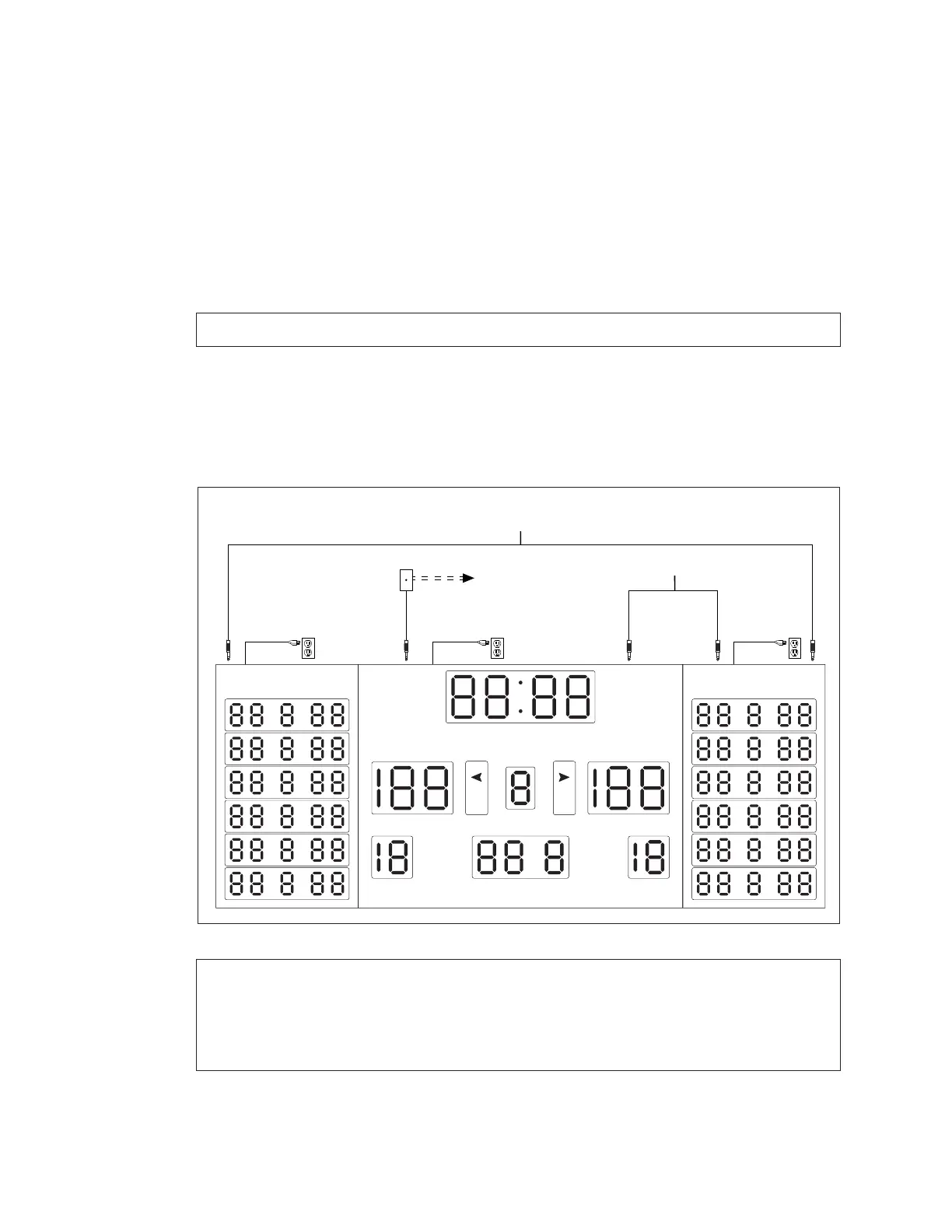
Figure 13 shows the connections required between a scoreboard and two statistics
displays. The same signal cable routing applies to hockey scoring modules. Refer to
Figure 9 for more information about connecting the signal wiring that runs from the
scoreboard to the controller. Refer also to DWG-124688 in Appendix B.
1� For wired signal connection to the main scoreboard, rst follow Steps 1–6 in Wired
Signal Connection (p�10).
Note: For wireless setups, refer to Wireless Signal Connection (p�11).
2� Connect a 1/4" phone plug cable between the J32 – SIGNAL OUT jack on top of the
main scoreboard to the J31 – SIGNAL IN jack on top of the right (GUEST) stat panel or
scoring module.
3� Connect another 1/4" phone plug cable between the J32 – SIGNAL OUT jack on top
of the right (GUEST) stat panel or scoring module to the J31 – SIGNAL IN jack on top of
the left (HOME) stat panel or scoring module.
Note: If any scoring modules are to be mounted below the main scoreboard,
ensure the right (GUEST) scoring module has a signal cable connected to the
SIGNAL IN jack and another cable running from the SIGNAL OUT jack to the
SIGNAL IN jack of the left (HOME) scoring module prior to securing the upper
scoreboard cabinet(s).
daktronics
GUESTHOME
PLYR FLS PTS PLYR FLS PTS
PERIOD
FOULS
PLAYER FOUL FOULS
SCORE SCORE
MATCH
BB
*Standard Cable Lengths:
10' (W-1340) 20' (W-1236)
30' (W-1238) 50' (W-1237)
J31 -
SIGNAL IN
J31 -
SIGNAL IN
J31 -
SIGNAL IN
J32 -
SIGNAL OUT
J32 -
SIGNAL OUT
Signal Cable*
Signal Cable*
[To Controller]
Wireless Control Also Available
Figure 13: Statistic Display Installation