Version 06 teledynedalsa.com/ipd 11
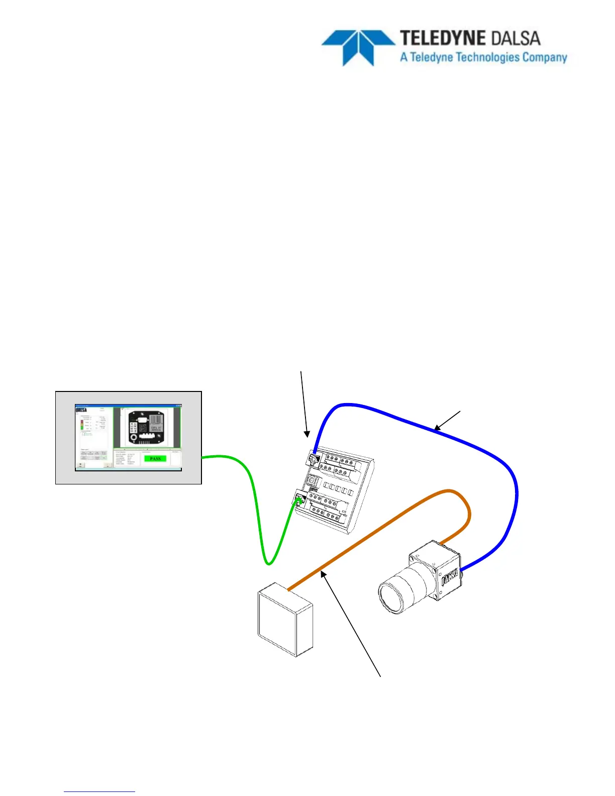
Ethernet Only Setup with Lamp
1.
Connect the M12-8 male end of the Ethernet cordset
(A-BVS-E8S-X) to the M12-8
female connector labeled “LAN”
on the camera.
2.
Connect the RJ45 end of the Ethernet cordset
to the RJ45 connector labeled
“CAM LAN”
on the Panel Link breakout module (A-BVS-PL-100)
3.
Connect the RJ45 labeled “LAN”
on the breakout module to the controlling PC,
PLC or the factory LAN
4.
Connect camera PWR and GND to the breakout screw terminals labeled “PWR”
5.
Connect the Lamp via corset A-BVS-L5S-X between the camera (M12-5 and the
lamp)
BOA System
A-BVS-E8S-X
A-BVS-PL-100
Setup Computer,
PLC or Factory
Network
Cat5 Cable
LED Lamp
A-BVS-L5S-X