Version 06 teledynedalsa.com/ipd 8
Installation
This section details how to connect the BOA vision system with its associated
components and factory environment.
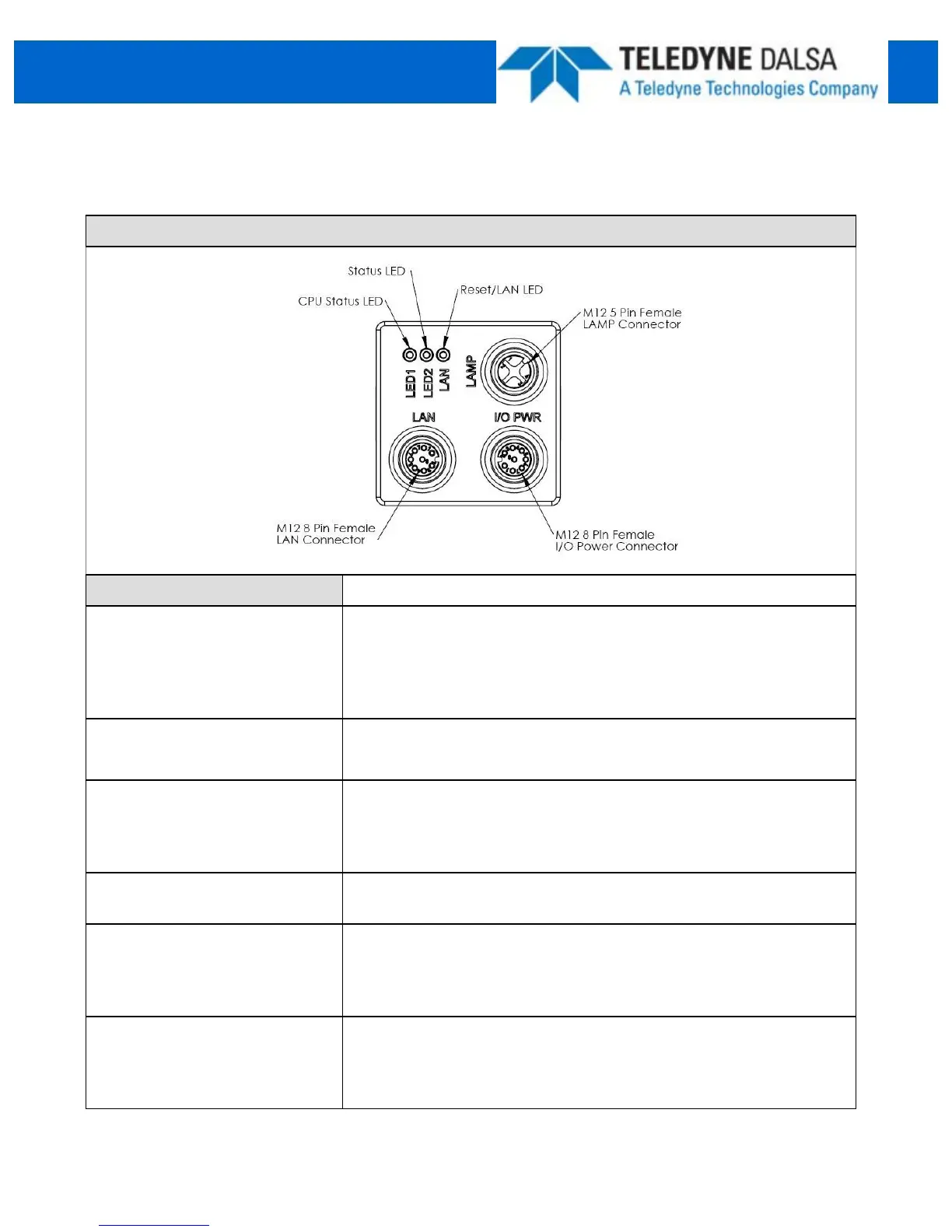
DefinitionsDesignator
LAN
10/100 BaseT
Ethernet connection. Provides the primary
interface for configuring the camera, developing the application
and monitoring results.
NOTE: The camera can be powered from the Ethernet cable
directly (Passive Power over Ethernet)
I/O PWR
Provides access to the camera I/O –
2 IN, 2 OUT Opto. Also
provides PWR input (12-30V).
LAMP Provides PWR and strobe control to a local LED light source.
NOTE: Lamp PWR is identical to BOA PWR input. The camera
should be powered from a 12V PWR source if the light requires
a 12V supply (Recommend 24V supply)
LAN LED Red/Green/Yellow = Network activity
Blue = Warm Reset
LED2 Green = Inspection Pass (runtime)
Blue blink = Booting (should stop after 20 seconds)
Blue = Inspection Recycle (runtime);
Red = Inspection Fail (Runtime)
LED1
Connecting the BOA Vision System
Camera Connectors and Indicators
Blue Solid = Camera booted, not configured
Green blink = Solution loaded, acquisition in process
Green Solid = Solution loaded
Red = Camera Fault