Version 06 teledynedalsa.com/ipd 20
Output Specifications
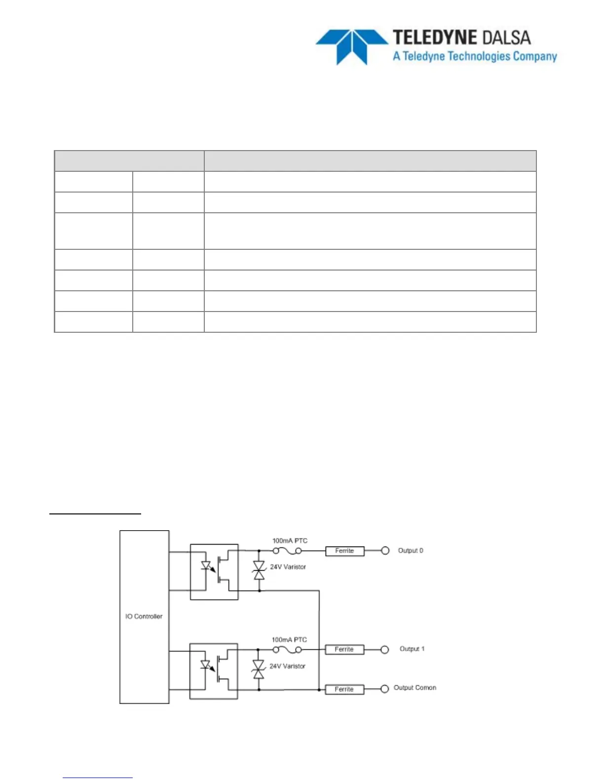
The BOA vision system provides two dedicated opto-isolated, solid state relay outputs
and a separate dedicated light strobe (pin 2 of lamp connector).
Specification Definition
Voltage (Vin) Load 24V maximum
Current GPO[0:1] 100mA max (drives to OCMN when active)
STRB 100mA max (drives to Vin when active)
NOTE: Strobe timing selected in iNspect
Sensor Panel
Protection Fuse PTC fuses to 100mA (GPO) & 100mA (STRB)
Common pin Out PWR or GND
Switch Time ON 10 Microsecond
OFF 50 Microseconds
The active polarity of each output is configured in the iNspect
application as detailed on
the following page.
To connect with an NPN input source, connect the camera output (pin 4 or 6) to the
NPN source input and the camera common output (pin 8) to GND. When the camera
output turns ON, the opto
switch closes and OUTX = 0 (current flows through load)
To connect with an PNP input source, connect the camera output (pin 4 or 6) to the
PNP source input and the camera common output (pin 8) to PWR. When the camera
output turns ON, the opto
switch closes and OUTX = output common.
Output Diagram