EasyManuals Logo

Dalsa BOA User Manual

Dalsa BOA
26 pages
To Next Page IconTo Next Page
To Previous Page IconTo Previous Page
Page #23 background imageLoading...
Page #23 background image
Version 06 teledynedalsa.com/ipd 23
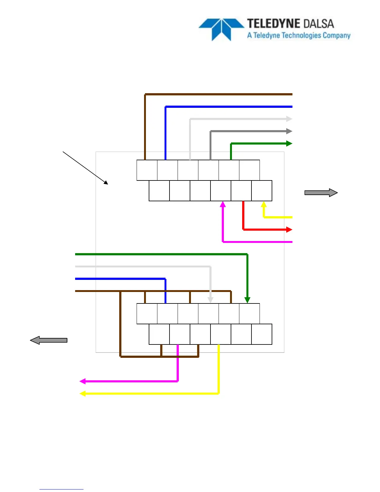
Panel Link Wiring Illustration
24V GND TRG ICMN IN0 ERTH
24V GND NC OUT0 OCMN OUT1
24V
24V GND TRG+ TRG- IN0+ IN0-
OU0+ OU0- OU1+ OU1- NC ERTH
OUT1-
OUT0-
GND
OUT0
OUT1
To BOA
PL-100
OCMN
TRG
To Control Panel
24V
GND
ICMN
IN0
TRG-
IN0-
Note: Cable color code on panel side is user defined.
Note: BOA side is a 1:1 connection using A-BVS-IO8
PL Ethernet ports not
shown

Questions and Answers:

Question and Answer IconNeed help?

Do you have a question about the Dalsa BOA and is the answer not in the manual?

Dalsa BOA Specifications

General IconGeneral
BrandDalsa
ModelBOA
CategoryDigital Camera
LanguageEnglish

Related product manuals