Version 06 teledynedalsa.com/ipd 22
Panel Link Specifications
The PL-100 module offers additional isolation for the BOA camera and simplifies wiring
at the control panel. The module also provides power over Ethernet for single cable
applications.
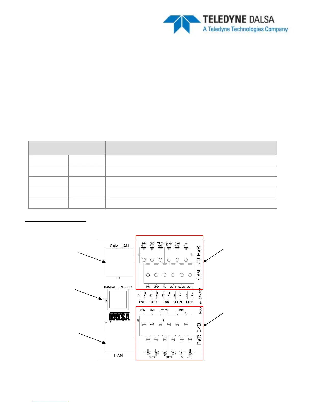
I/O connections to the BOA camera should be wired to the TOP connectors on the PL-
100 (J2 and J3) directly. NOTE: Avoid reversing PWR/GND on the I/O connector. Doing
so may make the PoE
feature unusable. In this case power must always be supplied
through the IO cable.
I/O connections in the control panel (outside word) should be wired to the BOTTOM
connectors on the PL-100 (J5 and J6). Specification for these signals are as follows:
Specification Definition
Voltage Load 24V maximum
Current GPO[0:1] 100mA max
Protection Fuse PTC fuses to 100mA (GPO)
Common
ICMN/OCMN
PWR or GND as wired on respective OPTOs
Switch Time GPO[0:1] 100 Microsecond (ON or OFF)
PL-100 Connections
Ethernet
connection to BOA
Manual Trigger for
debugging
Ethernet
connection to PC
I/O connections to
BOA (A-BVS-IO8)
I/O connections to
control panel