Version 06 teledynedalsa.com/ipd 19
Input Specifications
The BOA vision system provides two dedicated opto-isolated, polarity independent
inputs. One of the inputs provides the acquisition Trigger function, while the other is
general purpose.
Specification Definition
Voltage ON 12-30 V
OFF 0-3 V (12 V nominal threshold)
Current ON 7.5 mA
typ
(24 V applied)
Protection Resistance 3K Ohms
Isolation 4000 V RMS
Common pin Input PWR or GND
Switch Time ON 10 Microsecond
OFF 50 Microseconds
Latency Trigger 62 Microseconds from trigger input to start of acquisition
The active polarity of each input is configured in the iNspect
application. The camera
includes a noise filter on the input which is also configurable.
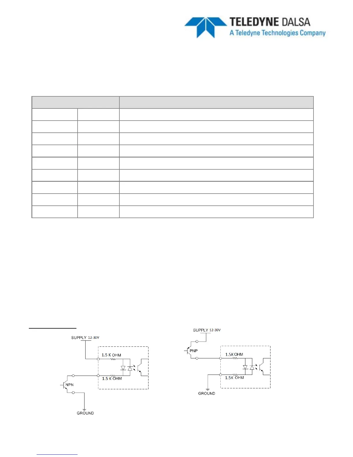
To connect with an NPN source, connect the camera trigger input (pin 1) to the NPN
source output and the camera common input (pin 5) to PWR. When the source output
turns ON, the camera input will be pulled down turning the opto-coupler ON.
To connect with an PNP source, connect the camera trigger input (pin 1) to the PNP
source output and the camera common input (pin 5) to GND. When the source output
turns ON, the camera input will be pulled up turning the opto-coupler ON.
Input Diagram
NPN Wiring PNP Wiring